
Apparatus and method for plasma treatment

a plasma treatment and apparatus technology, applied in the field of apparatus and apparatus for plasma treatment, can solve the problems of reducing the etch rate of photo resist at the periphery of the wafer, affecting the material contained in the treatment gas, and affecting the effect of fluorine radicals generated by plasma bombardment on the deposi

Inactive Publication Date: 2001-08-23
TOKYO ELECTRON LTD
View PDF2 Cites 50 Cited by
  • Summary
  • Abstract
  • Description
  • Claims
  • Application Information

AI Technical Summary

Problems solved by technology

For instance, in the etching process, a decrease of an etch rate of photo resist at a periphery of the wafer W or a difficulty in forming a contact hole is caused.
However, on the other hand, when the compensation ring is cooled, the fluorine radicals generated due to plasma bombardment on the deposit that is formed by deposition of material contained in the treatment gas become to largely affect.
That is an antinomic problem.

Method used


Image

  • Apparatus and method for plasma treatment
  • Apparatus and method for plasma treatment
  • Apparatus and method for plasma treatment

Examples


Embodiment Construction

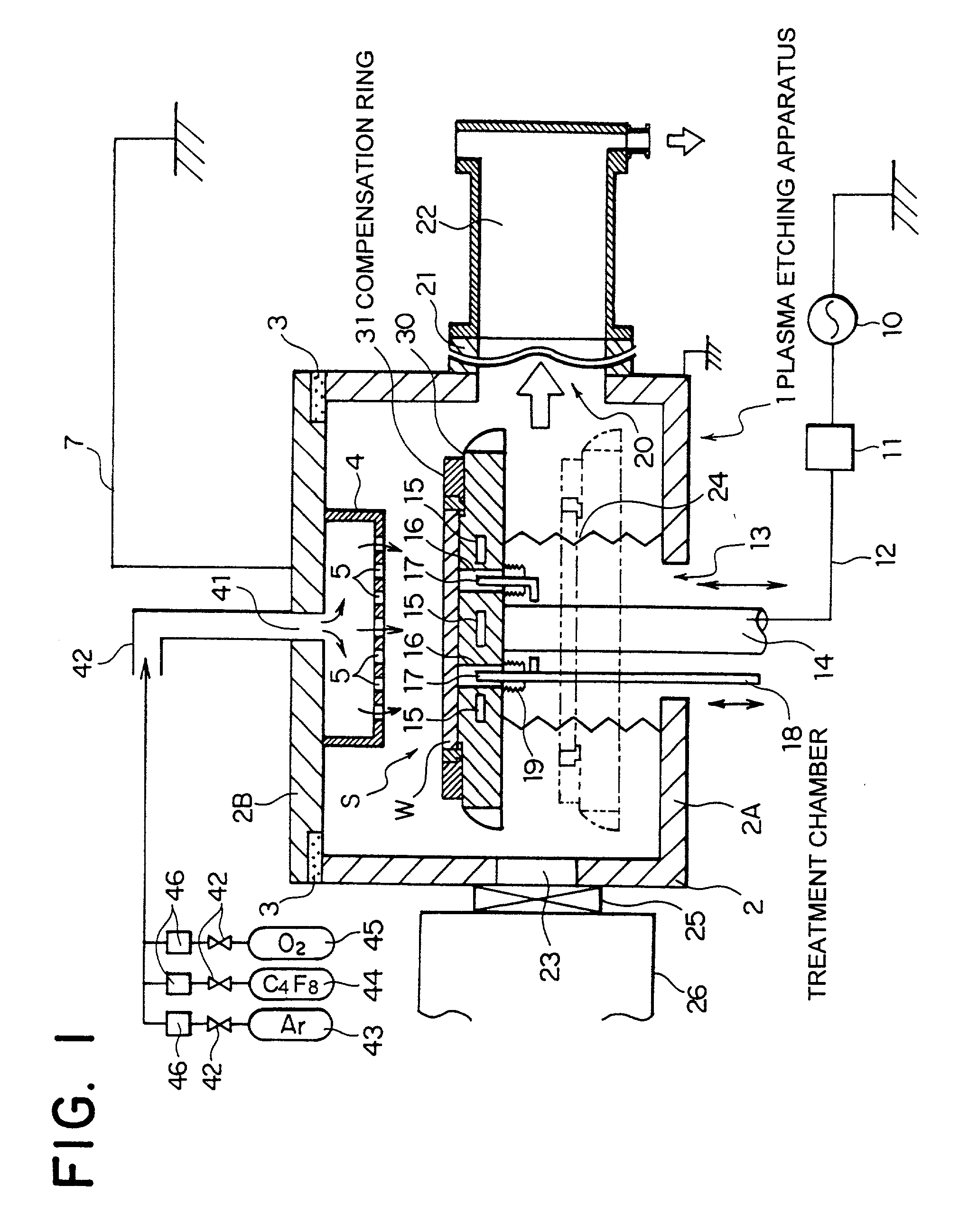
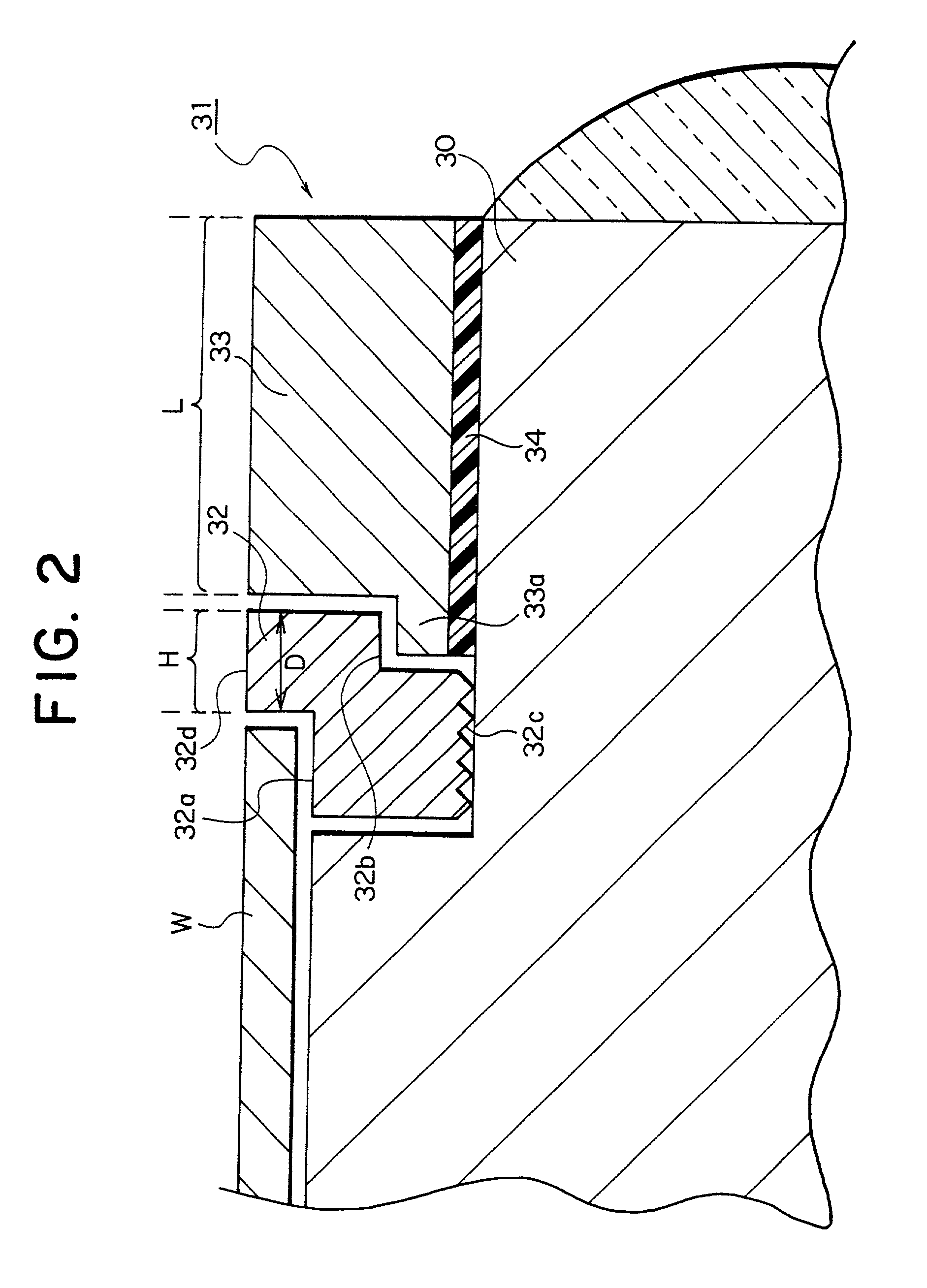
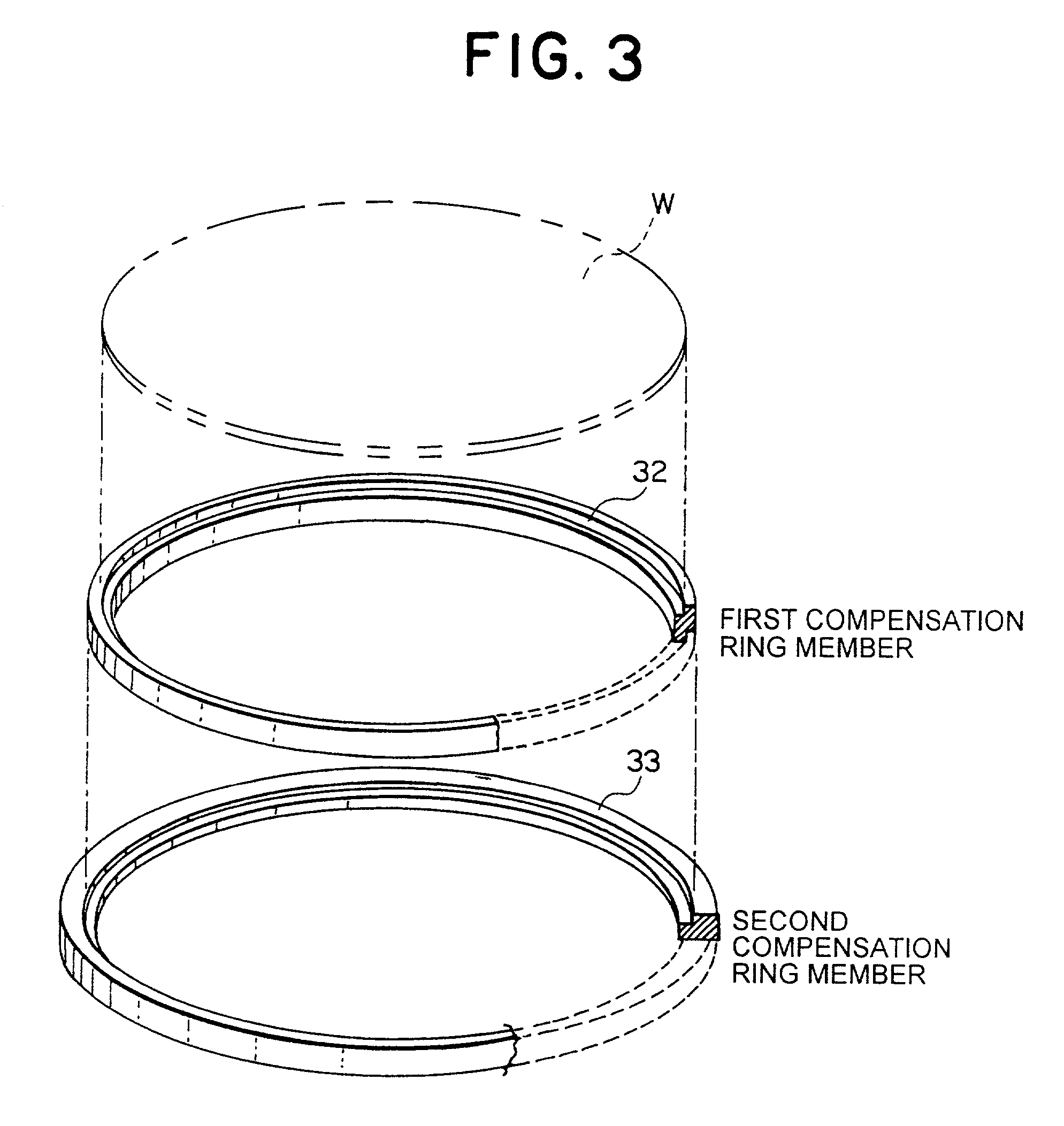
[0030] Apparatus for plasma treatment of the present invention comprises a treatment chamber, a treatment gas feeder, a plasma generating means, a susceptor, a first ring member and a second ring member. Here, in the treatment chamber, under an approximate vacuum, treatment is applied to a substrate to treat. The treatment gas feeder feeds the treatment gas to the substrate to treat. The plasma generating means generates plasma in the treatment chamber. On the susceptor, the substrate to treat is disposed. The first ring member surrounds a periphery of the substrate to treat disposed on the susceptor and is maintained at a first temperature during treatment. The second ring member surrounds a periphery of the first ring member and is maintained at a second temperature during the treatment.

[0031] In the aforementioned apparatus for plasma treatment, for instance the first temperature is set higher than the second one.

[0032] Furthermore, in the aforementioned apparatus for plasma trea...


PUM

PropertyMeasurementUnit
widthaaaaaaaaaa
frequencyaaaaaaaaaa
widthaaaaaaaaaa

Abstract

A compensation ring 31 disposed to surround a periphery of a wafer W on a susceptor 30 is concentrically divided into an inside first compensation ring member 32 and an outside second compensation ring member 33. A width of a first compensation ring member 32 is made such thin as one to three times mean free path of treatment gas molecules, thereby suppressing heat transfer between a susceptor 30 and a second compensation ring member 33. A base of a second compensation ring member, through a layer of conductive silicone rubber 34, is made to come into an intimate contact with an upper surface of a susceptor 30, thus helping to cool.

Description

[0001] 1. Field of the Invention[0002] The present invention relates to apparatus and a method for plasma treatment of a substrate to treat such as a semiconductor wafer or the like, more specifically relates to apparatus and a method for plasma treatment of a substrate to treat by the use of plasma.[0003] 2. Description of the Related Art[0004] So far, in apparatus for treatment of a substrate to treat such as a semiconductor wafer or the like, for instance in apparatus for plasma treatment such as plasma-etching apparatus, it is usual to dispose an annular compensation ring on a susceptor thereon the wafer W is disposed. The compensation ring is a ring that is disposed in the surroundings of the wafer to compensate characteristics of plasma generated in a treatment chamber. For instance, by means of impedance of the ring, an electric field is concentrated on the wafer to help plasma distribute intensively on the wafer. Thereby, the plasma operates intensively on the wafer disposed...

Claims


Application Information

Patent Timeline
Patent Type & Authority Applications(United States)
IPC IPC(8): C23C16/458C23C16/509H01L21/205H01J37/32H01L21/00
CPCC23C16/4585C23C16/5096H01J37/32642H01L21/67069
Inventor DENPOH, KAZUKI
Owner TOKYO ELECTRON LTD
Learn More