Super-resolution spectral imaging system and super-resolution spectral imaging method based on scattering medium

A spectral imaging and super-resolution technology, applied in the field of super-resolution spectral imaging, can solve the problems of high structural complexity of the optical system, reducing the signal-to-noise ratio of the target signal to be measured, unfavorable and accurate reconstruction of spectral signals, etc., reaching the scope of application wide, simple structure, easy operation

Active Publication Date: 2018-04-13
XIDIAN UNIV
View PDF5 Cites 21 Cited by
  • Summary
  • Abstract
  • Description
  • Claims
  • Application Information

AI Technical Summary

Problems solved by technology

[0006] All of the above methods can achieve spectral imaging, but they all have shortcomings. For example, because one imaging can only obtain a one-dimensional or two-dimensional subset of the complete three-dimensional data cube, in order to obtain the complete spectral image of the target, it is necessary to scan time. , such as push broom, staring scan, etc. At the same time, with the improvement of spatial resolution and spectral resolution, the frame rate requirements of detectors are also getting higher and higher, and the transmission of large quantities has become a big problem, which limits the traditional Applications of supe

Method used


Image

  • Super-resolution spectral imaging system and super-resolution spectral imaging method based on scattering medium
  • Super-resolution spectral imaging system and super-resolution spectral imaging method based on scattering medium
  • Super-resolution spectral imaging system and super-resolution spectral imaging method based on scattering medium

Examples


Embodiment 1

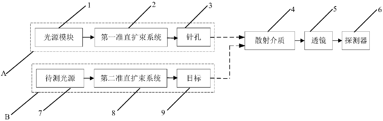
[0047] See figure 1 , figure 1 A schematic structural diagram of a super-resolution spectral imaging system based on a scattering medium provided by an embodiment of the present invention. The super-resolution spectral imaging system includes a calibration branch A, a test branch B, a scattering medium 4 , a lens 5 and a detector 6 . Wherein, the calibration branch A includes the light source module 1 , the first collimator beam expander system 2 and the pinhole 3 , and the test branch B includes the test light source 7 , the second collimator beam expander system 8 and the target 9 . The light source module 1 passes through the first collimator beam expander system 2 and then passes through the pinhole 3 to become a point light source, and then passes through the scattering medium 4 for encoding, and the lens 5 for imaging. According to the speckle collected by the detector 6, it can be measured to obtain The point spread function of the light source module 1 at different w...

Embodiment 2

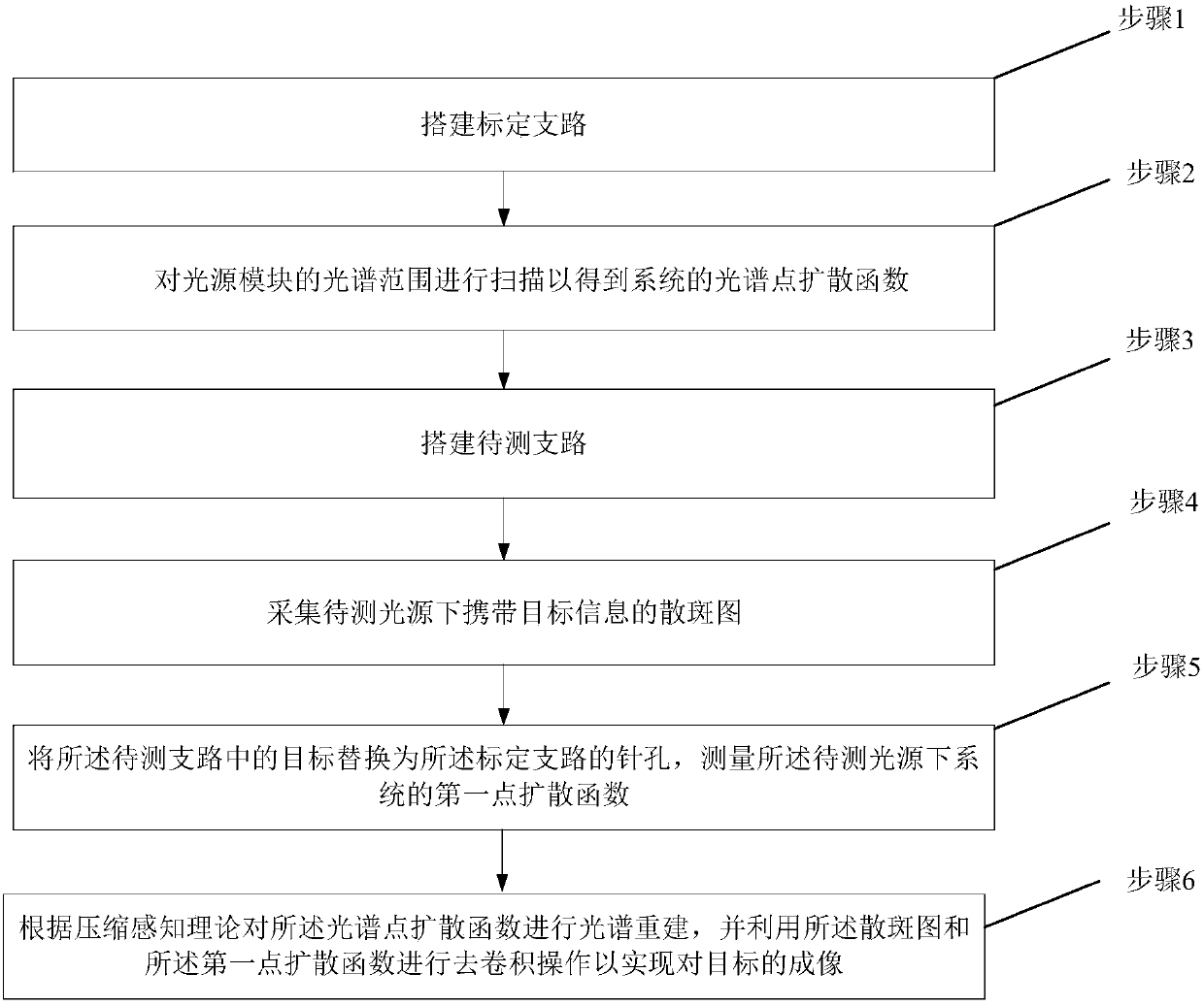
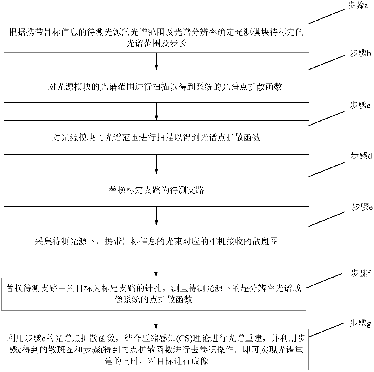
[0058] Please also see figure 2 and image 3 , figure 2 A schematic diagram of a super-resolution spectral imaging method based on a scattering medium provided by an embodiment of the present invention, image 3 It is a schematic diagram of another super-resolution spectral imaging method based on a scattering medium provided by an embodiment of the present invention. The super-resolution spectral imaging method based on the scattering medium of the present invention operates on any of the above-mentioned super-resolution spectral imaging systems based on the scattering medium. Spectral imaging methods include:

[0059] Step 1: Build a calibration branch;

[0060] Step 2: Scan the spectral range of the light source module to obtain the spectral point spread function of the system;

[0061] Step 3: Build the branch to be tested;

[0062] Step 4: Collect the speckle pattern carrying the target information under the light source to be tested;

[0063] Step 5: replacing t...

Embodiment 3

[0093] See Figure 4 , Figure 4 It is a schematic diagram of a method for forming a spectral point spread function provided by an embodiment of the present invention. In this embodiment, on the basis of the above embodiments, the formation of the spectral point spread function is mainly described as follows:

[0094] Step 21: According to the step size, adjust the light source module so that it sequentially outputs the center wavelength at intervals of the step size;

[0095] Step 22: Use the detector to collect the intensity distribution diagram corresponding to the light of each central wavelength, and obtain the second point spread function of different central wavelengths;

[0096] Step 23: Combining the second point spread functions of different central wavelengths to form the spectral point spread function.

[0097]According to the step size, the light source module 1 is controlled so that it sequentially outputs the center wavelengths at intervals of the step size, ...


PUM

PropertyMeasurementUnit
Diameteraaaaaaaaaa

Abstract

The present invention relates to a super-resolution spectral imaging system and a super-resolution spectral imaging method based on a scattering medium. The super-resolution spectral imaging system comprises a calibration branch A, a scattering medium 4, a lens 5, a detector 6 and a branch B to be detected, wherein the calibration branch A comprises a light source module 1, a first collimation beam expansion system 2 and a pinhole 3, and the branch B to be detected comprises a light source 7 to be detected, a second collimation beam expansion system 8 and a target 9. According to the embodiments of the present invention, the point spread functions of the system are measured when the light source module outputs different wavelengths so as to construct the spectral point spread function (SPSF), the spectral reconstruction is achieved by using the compressed sensing (CS) method while the scattering medium with the appropriate scattering mean free path is matched, and the speckle receivedby the camera is subjected to convolution removing by using the point spread function corresponding to the wavelength of the light source to be detected, such that the maximum super-resolution imagingcan be achieved without the increase of the complexity of the system; and the super-resolution spectral imaging system has advantages of simple structure, easy control, low component cost, strong anti-disturbance capability and wide application field.

Description

technical field [0001] The invention belongs to the technical field of super-resolution spectral imaging, and in particular relates to a super-resolution spectral imaging system and method based on a scattering medium. Background technique [0002] Spectral imaging technology can obtain the spatial information and spectral information of the target, and can classify substances according to their unique spectral characteristics. At present, it has been widely used in civil, military, marine and criminal investigations. Traditional Spectral Imaging Techniques Imaging spectroscopy techniques can be divided into three categories: dispersion type, filter type and interference type. [0003] The super-resolution spectral imaging method is the most widely used. It is a kind of dispersion-type spectroscopic technology, including prism spectroscopic technology and grating spectroscopic technology. Diffusion; grating spectroscopic technology uses the principle of diffraction to scatt...

Claims


Application Information

Patent Timeline
IPC IPC(8): G01N21/25G01N21/01
CPCG01N21/01G01N21/25
Inventor 宫睿王剑南朱磊刘杰涛郭成飞
Owner XIDIAN UNIV
Why Eureka
Try Eureka