
Profiling arrangement with a roll forming machine and with a welding device

a technology of profiling or forming arrangement and roll forming machine, which is applied in the direction of resistive welding apparatus, structural elements, building components, etc., can solve the problems of keeping machine costs within limits, and achieve the effect of saving welding energy, increasing the feeding speed of workpieces, and prolonging the effective time on workpieces

Inactive Publication Date: 2001-09-13
DREISTERN WERK MASCHENBAU
View PDF0 Cites 24 Cited by
  • Summary
  • Abstract
  • Description
  • Claims
  • Application Information

AI Technical Summary

Benefits of technology

[0007] In this way, shaped workpieces formed from practically endless sheet material can be provided and stabilized with two weld joints without requiring two separate correspondingly expensive and mechanically complicated welding devices. By applying two weld joints to a roller-shaped workpiece, for example, a hollow shaped workpiece with crosspiece, a considerable improvement in the stiffness of this workpiece is obtained, and overlapping areas for producing folds are simultaneously avoided so that material can also be saved in this way. Nevertheless, machine costs are kept within limits because only a single welding device is required.
[0022] Especially upon combination of a few or several of the above-described features and measures, a profiling arrangement is obtained with a roll forming machine and a welding device with which longitudinally welded workpieces or tubes can be provided with two or more weld joints which can be designed as a stitched joint or as a continuous joint. Since the welding energy produced in the welding device is split up, a considerable saving of weight and costs is possible in that, in spite of possible material savings, a greater stiffness and torsional strength of the shaped workpiece to be produced can be attained through the introduction of multiple weld joints. Nevertheless, there is practically no additional expense for equipment compared to a profiling installation with one welding device.

Problems solved by technology

Nevertheless, machine costs are kept within limits because only a single welding device is required.

Method used


Image

  • Profiling arrangement with a roll forming machine and with a welding device
  • Profiling arrangement with a roll forming machine and with a welding device
  • Profiling arrangement with a roll forming machine and with a welding device

Examples


Embodiment Construction

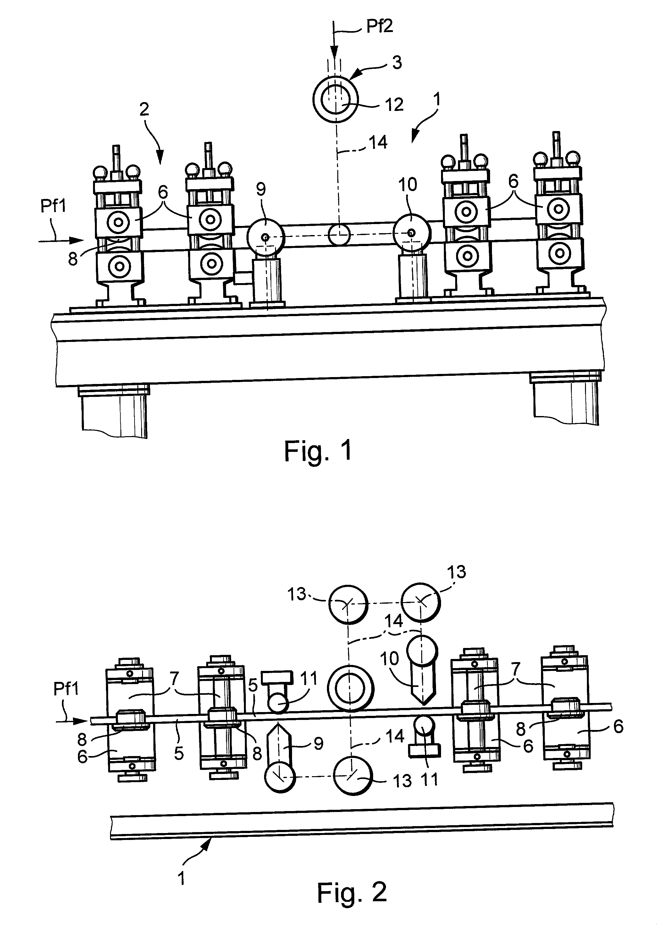
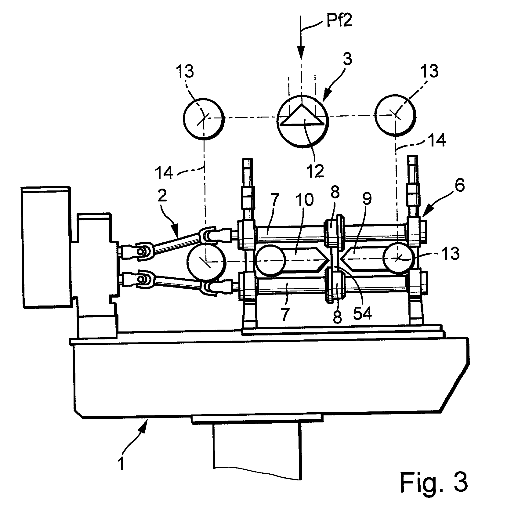
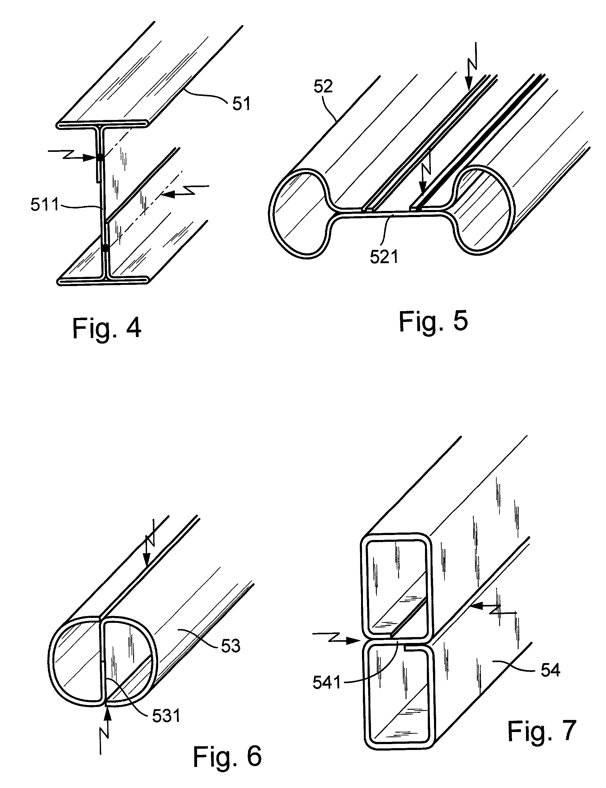
[0028] A profiling arrangement designated as a whole by 1 is provide which includes a roll forming machine 2 and a welding device positioned in its processing path and designated as a whole by 3. The arrangement serves in manufacturing shaped workpieces 51, 52, 53, or 54 formed from a sheet-metal strip 5 and represented in FIGS. 4-7, with additional workpiece cross-sections also being possible.

[0029] The roll forming machine 2 includes tools 6 positioned one behind the other in the feeding direction of the workpiece 5 indicated by arrow Pf1. The tools include, in each case, at least two driven or freely rotating forming rollers 8 arranged on parallel axes 7. In FIGS. 1 and 2, one recognizes such tools 6 both ahead of as well as behind welding device 3, the tools 6 located ahead of the welding device 3 in the feeding direction forming the actual workpiece while the tools 6 located behind the welding device 3 serving in calibrating and / or aligning the welded workpiece.

[0030] In FIGS. ...


PUM

PropertyMeasurementUnit
Speedaaaaaaaaaa
Areaaaaaaaaaaa
Heightaaaaaaaaaa

Abstract

A profiling arrangement (1) with a roll forming machine (2) including several roller-type forming tools (6) and with a welding device (3) positioned in its processing path makes possible the application of more than one weld joint to a workpiece (51, 52, 53, or 54) to be manufactured. The welding device includes a single energy source and this source is connected with at least two welding heads (9) and (10) for producing both weld joints. The energy produced by welding device (3) is divided over the individual welding heads (9 and 10). This is especially favorable in the case of a welding device (3) with a laser-beam source. The laser beam can be split into several partial laser beams and guided to the individual laser-beam welding heads.

Description

BACKGROUND[0001] The present invention relates to a profiling or forming arrangement with a profiling or forming machine and with a welding device in its processing path for manufacturing a shaped workpiece formed from a sheet-metal strip, the roll forming machine exhibiting roll tools positioned one behind the other in the feeding direction of the workpiece and the roll tools being formed in each case essentially by at least two driven or freely rotating forming rollers positioned on parallel axes.[0002] Many different types of such profiling arrangements are known and serve in forming and manufacturing a wide range of shaped workpieces, especially hollow shaped workpieces or tubes.[0003] From DE 198 34 400 C1, a profiling arrangement with a welding device for manufacturing tubes of this type in which the initially opposing edges of the workpiece are bent toward each other and then joined together with the aid of the welding device is known. Behind the welding device in the feeding...

Claims


Application Information

Patent Timeline
IPC IPC(8): B21C37/08B21C37/083B21C37/15B21D5/08B21D5/12B21D47/01B23K11/087B23K26/00B23K26/067B23K26/244B23K26/262
CPCB21C37/0803B21C37/083B21C37/151B21D47/01B23K26/067B23K26/0673B23K26/246B23K26/265B23K2201/06B23K2201/18E04C2003/0456B23K26/262B23K26/244B23K2101/06B23K2101/18
Inventor KUMMLE, RALF
Owner DREISTERN WERK MASCHENBAU
Learn More