Apparatus and method for transferring video data

a video data and apparatus technology, applied in the direction of data conversion, generating/distributing signals, instruments, etc., can solve the problems of disturbance of image circuit scale becomes large,

Inactive Publication Date: 2001-09-13
NEC CORP
View PDF4 Cites 28 Cited by
  • Summary
  • Abstract
  • Description
  • Claims
  • Application Information

AI Technical Summary

Problems solved by technology

However, as shown in FIG. 4, in the form in which a frame buffer is contained in the video data transfer apparatus, there is a disadvantage that it is not avoidable that the circuit scale becomes large.
Also, in the case of the format having an FIFO memory without employing a frame buffer in a video data transfer apparatus as shown in FIG. 5, there is a disadvantage that it is not avoidable that the circuit scale becomes large in order to avoid such an image disturbance when a band for video data transfer on a general purpose bus cannot be secured.
This is because since an overflow occurs in the FIFO memory when a band for video data transfer is not secured on a general purpose bus, video data is lost so that dislocation in display positions of each video datum on the video frame occurs, resulting in disturbance in an image.

Method used


Image

  • Apparatus and method for transferring video data
  • Apparatus and method for transferring video data
  • Apparatus and method for transferring video data

Examples


first embodiment

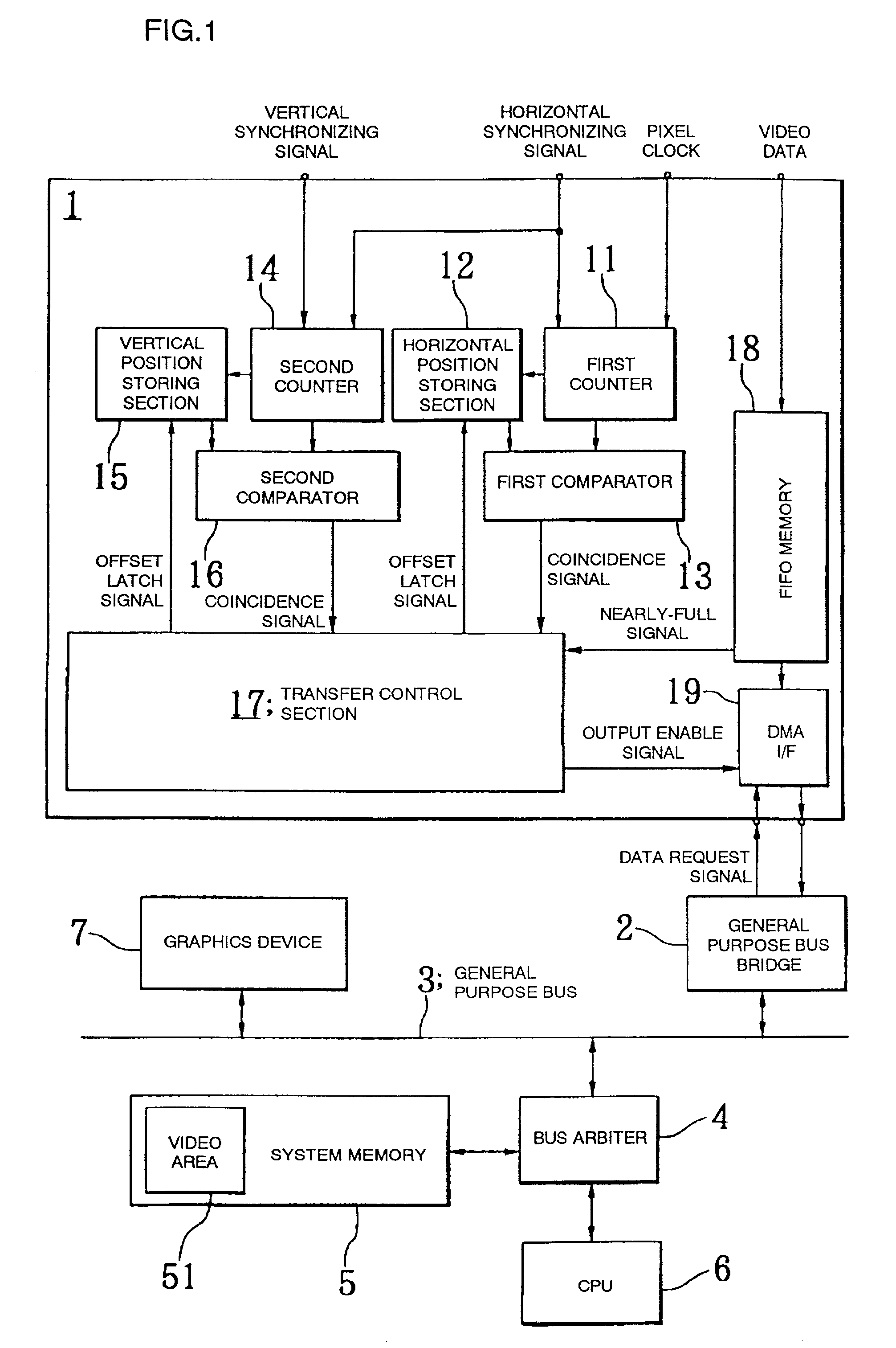
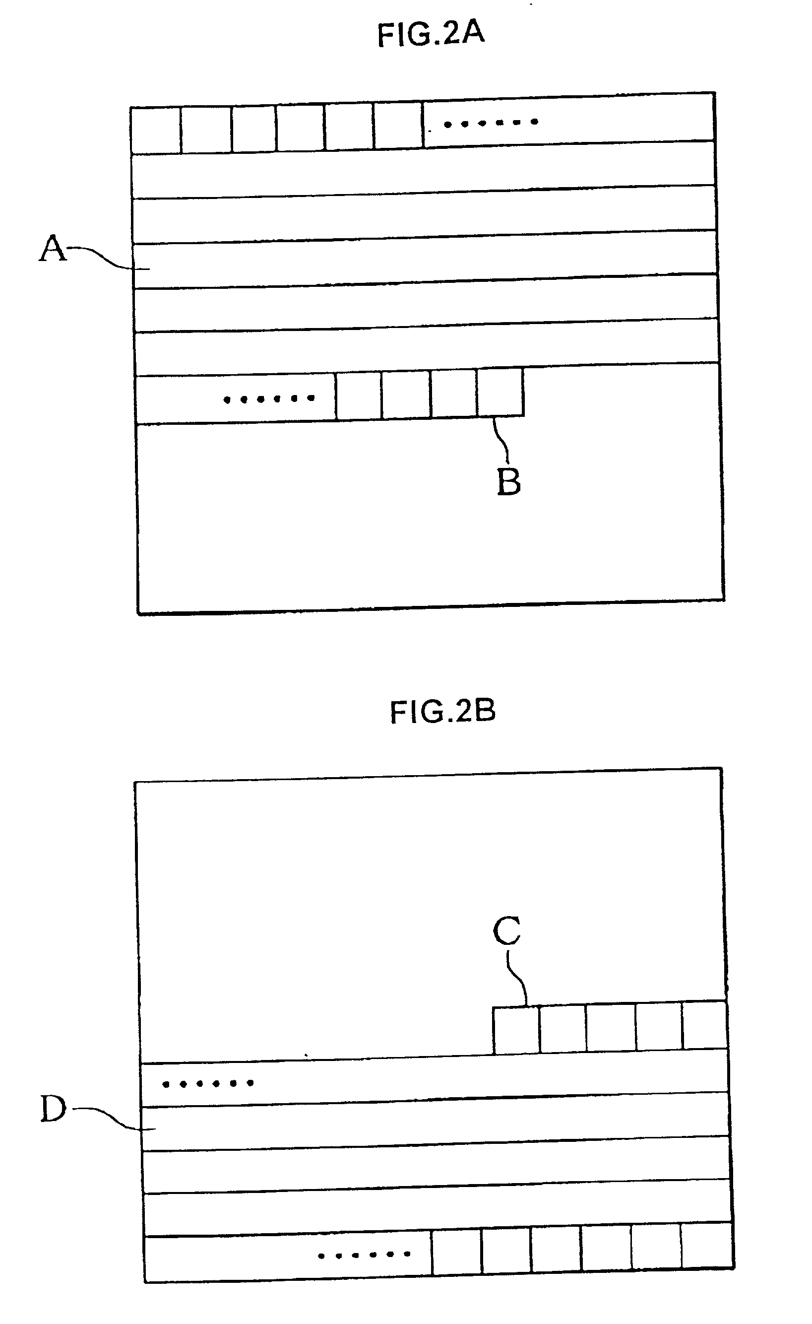
[0060] FIG. 1 is a block diagram showing a configuration of the present invention, and FIG. 2 is a diagram for explaining a transfer suspension and a transfer resumption of video data at the time of occurrence of a nearly-full signal.

[0061] FIG. 1 shows a schematically configuration of a computer apparatus at the time when transfer of video data is performed for a display apparatus, and shows that a video data transfer apparatus 1, a general purpose bus bridge 2, a general purpose bus 3, a bus arbiter 4, a system memory 5, and a CPU 6, and a graphics apparatus 7 are included.

[0062] The video data transfer apparatus 1 performs processing for transferring input video data to be overlay displayed to the general purpose bus bridge 2. The general purpose bus bridge 2 connects the video data outputted from the video data transfer apparatus 1 to the general purpose bus 3 in accordance with a predetermined access procedure between the general purpose bus. The general purpose bus 3 is connec...

second embodiment

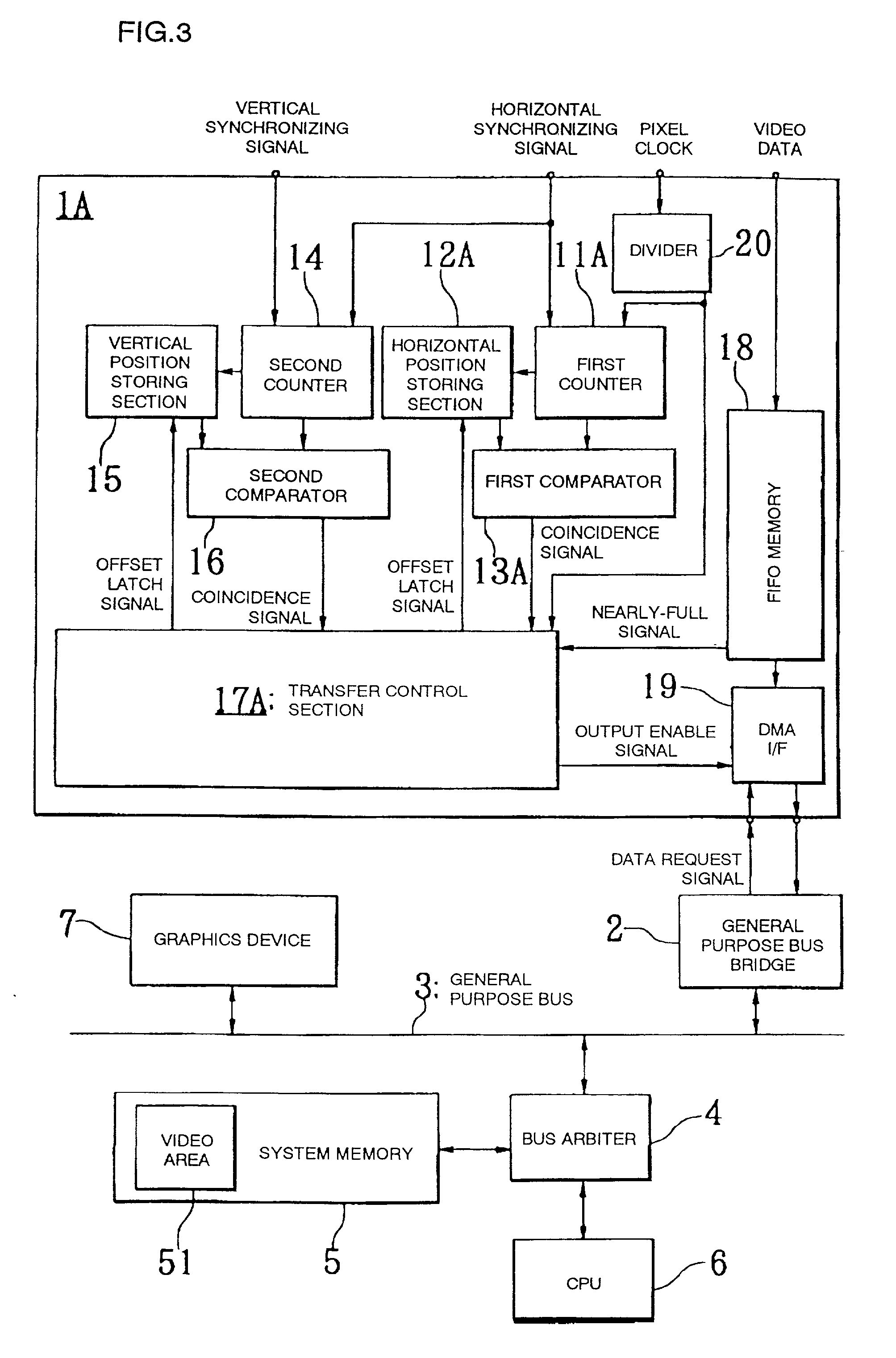
[0081] FIG. 3 is a block diagram showing a configuration of the present invention.

[0082] In this example, since the configuration of the computer apparatus for transferring vide data to a display apparatus is similar to that of the case of the first embodiment shown in FIG. 1, detail explanation regarding this will be omitted.

[0083] A video data transfer apparatus 1A of the present embodiment is schematically composed of a first counter 11A, a horizontal position storing section 12A, a first comparator 13A, a second counter 14, a vertical position storing section 15, a second comparator 16, a transfer control section 17A, an FIFO memory 18, and a DMA I / F 19, and a divider 20 as shown in FIG. 3.

[0084] The first counter 11A starts counting a divided clock from the divider 20 from a horizontal synchronizing signal to count the number of video data which have already been transferred in one line in the horizontal direction for each of plural bits corresponding to the division ratio of t...


PUM


Abstract

Overlay display can be performed correctly even in a heavy load state regarding video data amount on a general purpose bus. The video data transfer apparatus of the present invention comprises an FIFO memory for video data and outputting a nearly-full signal when held data become close to full and a transfer control section stopping an output enable signal so as to stop output from the FIFO memory at the time of output of the nearly-full signal and restoring the output enable signal so as to perform control in which the video data on and after an output stop position are outputted from the FIFO memory when the same position as the output stop position appears in a frame on and after the frame of the output stop time when the nearly-full signal disappears.

Description

[0001] 1. Technical Field of the Invention[0002] The present invention relates to a video data transfer apparatus and a transfer method for video data for performing an overlay display of an image on a display screen of a computer.[0003] 2. Description of the Prior Art[0004] In a computer apparatus, a video data transfer apparatus has been conventionally employed for performing an overlay display of additional images which has already been displayed on its display screen.[0005] FIG. 4 is a block diagram showing a configuration of a first conventional example, shows a schematically configuration of a computer apparatus in such a case when transfer of video data is performed for a display apparatus, and shows that a video data transfer apparatus 100, a graphics apparatus 200, a general purpose bus 300, a bus arbiter 400, a system memory 500, and a central processing unit (CPU) 600 are included.[0006] The video data transfer apparatus 100 performs processing for transferring video data...

Claims


Application Information

Patent Timeline
Patent Type & Authority Applications(United States)
IPC IPC(8): G06F1/04G06F3/14G06T1/60G06F3/153G06F5/06G06F5/14G06F13/28G06F13/38G06F13/42G09G5/00G09G5/36G09G5/377
CPCG06F3/14G06F5/06G06F5/14G09G2340/125
Inventor ONAGAWA, SEIKI
Owner NEC CORP
Why Eureka
Try Eureka