Display panel including liquid crystal material having spontaneous polarization

a liquid crystal material and display panel technology, applied in the field of liquid crystal devices, can solve the problems of low manufacturing cost, low image degradation, and low response time of stn driven through the simple matrix, and achieve the effect of low manufacturing cost and low production cos

Inactive Publication Date: 2001-11-01
FUJITSU LTD
View PDF8 Cites 15 Cited by
  • Summary
  • Abstract
  • Description
  • Claims
  • Application Information

AI Technical Summary

Problems solved by technology

The liquid crystal display of STN driven through a simple-matrix-type electrode configuration, which is referred to as simple matrix, is liable to generate image degradation caused by electrical cross-talk between picture elements or pixels, while the relatively low manufacturing cost results from the use of the simple matrix.
The liquid crystal display of STN driven through the simple matrix also has undesirable response time (slow response time) for displaying dynamic images such as moving pictures.
The liquid crystal display device of TN further has faster response time than that of the liquid crystal display of STN, however the response time is limited by the characteristics of material itself, which means the liquid crystal display of TN being unsuitable for a display panel required to respond at high speed for displaying dynamic images such as motion picture.
These two materials have a common problem of a narrow view angle, hence the preferable view direction to see images on the display using these materials is limited.
However, the FLC material has a disadvantage such as a decrease of contrast ratio (or low contrast ratio) when used as the material for the display panel.
That is, a little increase of the light transmittance in the picture element occurs when data pulses of zero amplitude for displaying "black" during several frames are applied to the element, and a little amount of light from a light source leaks through the element, resulting in decreasing the contrast ratio.
The FLC has the disadvantage caused by the incomplete memory effect during driving for displaying "black" in several frames, where the light transmittance is preferably desired zero.

Method used


Image

  • Display panel including liquid crystal material having spontaneous polarization
  • Display panel including liquid crystal material having spontaneous polarization
  • Display panel including liquid crystal material having spontaneous polarization

Examples


Embodiment Construction

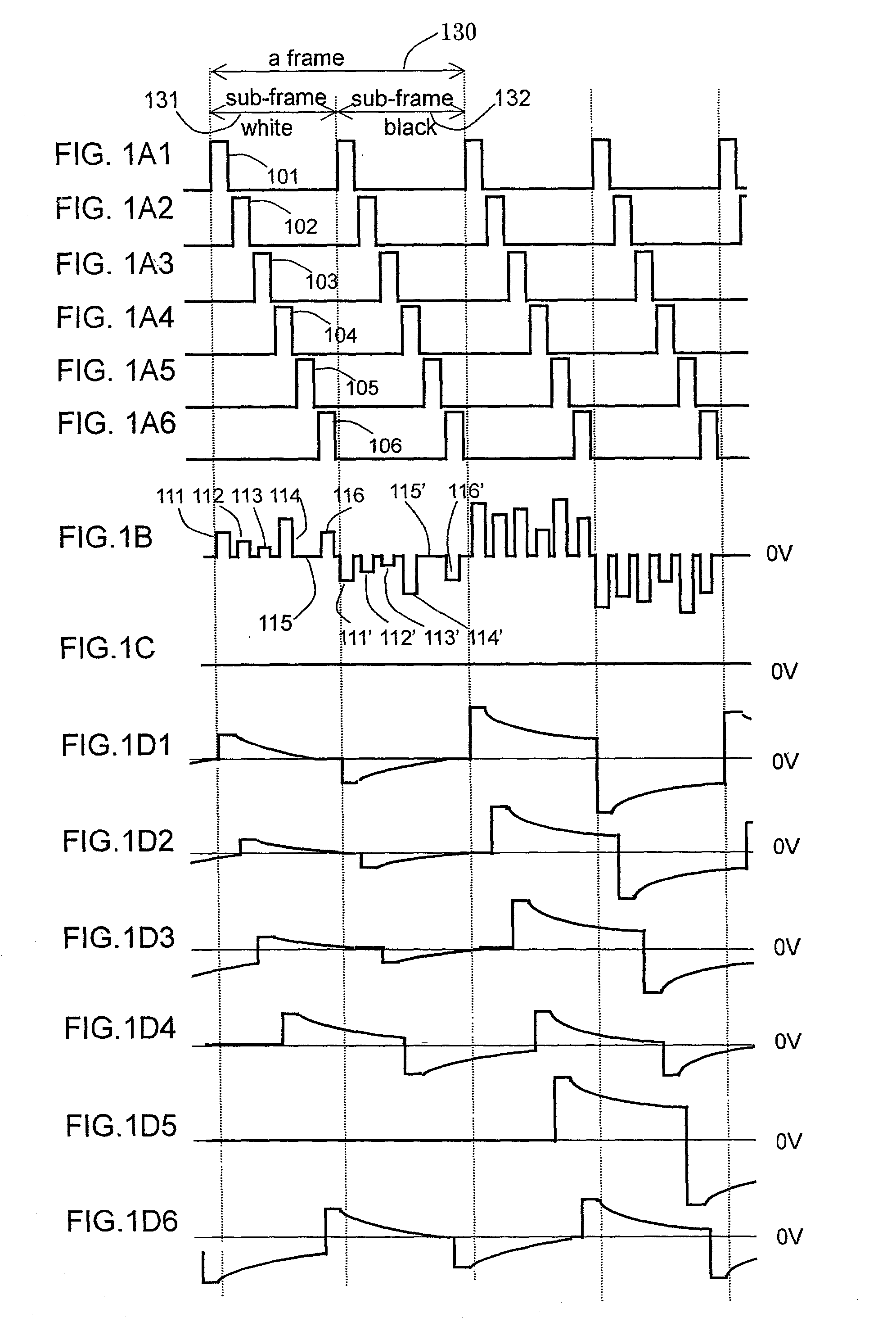
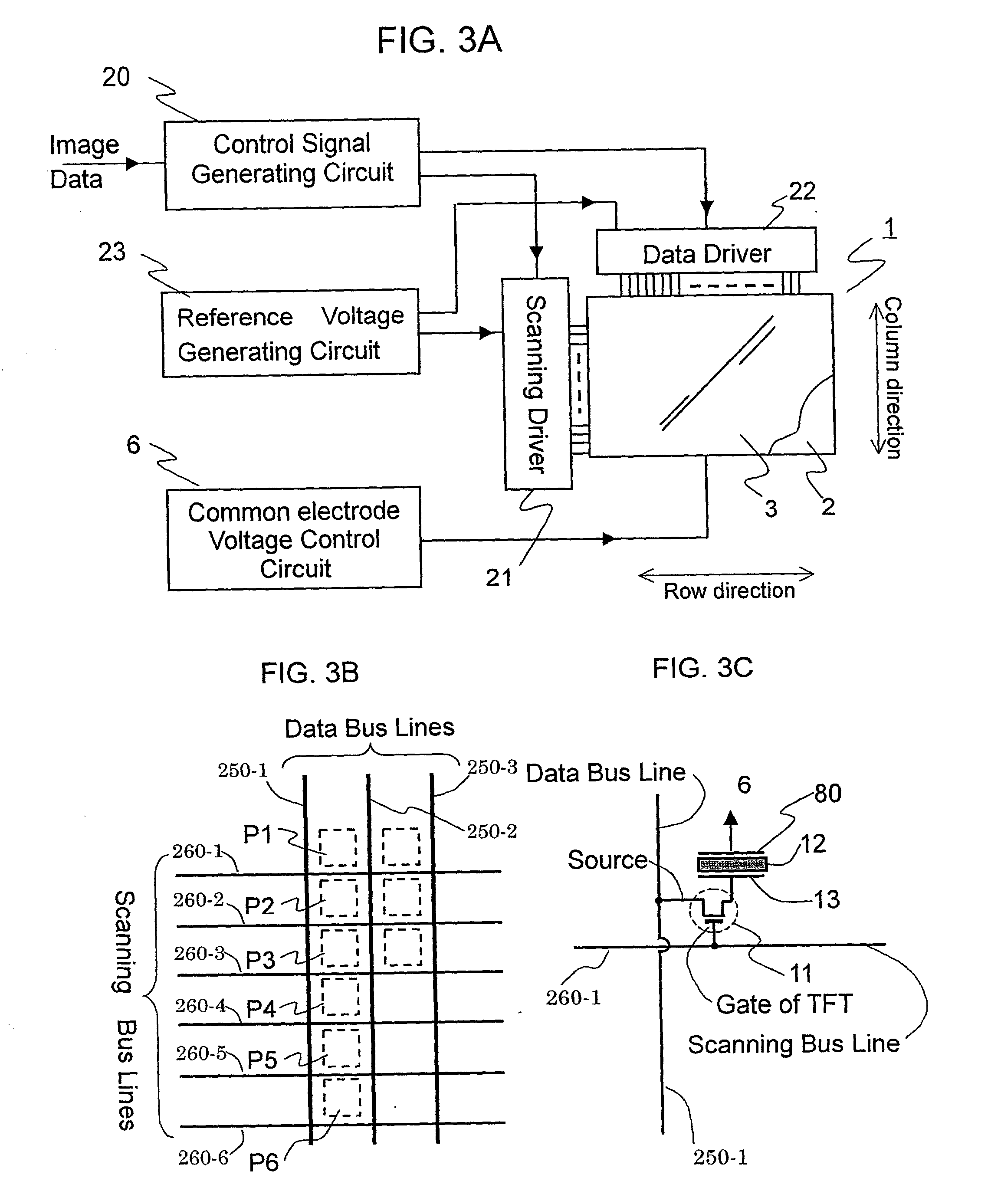
[0042] Referring to FIG. 1, the schematic waveforms are shown in case of a liquid crystal display using FLC material which is driven through the active matrix, where six picture elements P1 to P6 arranged on a same column direction as shown in FIG. 3B are driven for example.

[0043] More in detail, each of FIGS. 1A1 to 1A6 schematically show gate pulses or scan pulses 101 to 106 applied to relevant scanning bus line respectively, each of the scanning bus lines is electrically connected to each gate electrode of thin film transistors (TFTs) as switching devices in the active matrix. During the application of the gate pulse 101, for example, to a scanning bus line the relevant TFTs turn on, and turn off if no application of the gate pulse. As shown in FIGS. 1A1 to 1A6, the gate pulses 101 to 106 are applied in sequence to each scanning bus line, hence these gate pluses 101 to 106 sequentially scan from the first scanning bus line to the last scanning bus line, while FIGS. 1A1 to 1A6 sho...


PUM

PropertyMeasurementUnit
electrical potentialaaaaaaaaaa
thickaaaaaaaaaa
particle sizeaaaaaaaaaa

Abstract

There is provided a liquid crystal display including a panel using a liquid crystal material having spontaneous polarization, such as ferroelectroic liquid crystal (FLC); having a faster response time suitable to display dynamic images. The FLC has the disadvantage caused by the incomplete memory effect at during driving for displaying "black" in several frames, where the light transmittance is preferably desired zero. The panel in the display are driven signals so that the driving signals are applied across the picture element, where the signals are positively or negatively offset to reference voltage of the panel.

Description

[0001] 1. Field of the Invention[0002] This invention relates to liquid crystal devices, and particularly to devices using liquid crystal having spontaneous polarization such as ferroelectric or antiferroelectric liquid crystal materials.[0003] 2. Description of Related Art[0004] In recent years, the research on liquid crystal has rapidly progressed, resulting in increase of its application to devices, such as a display panel, an optical modulator, and an optical shutter in printing machine and so on.[0005] In particular, liquid crystal devices and liquid crystal panels are characterized by thin depth, a lightweight, and low consumption. Hence, the devices or the panels are used as a display unit in various kind of devices, such as mobile terminals, for example cellular phones and mobile computers, moreover desk-top computers or household television sets.[0006] The configuration of a liquid crystal display panel generally has a pair of opposing substrates spaced appropriately apart,...

Claims


Application Information

Patent Timeline
Patent Type & Authority Applications(United States)
IPC IPC(8): G09F9/30G02F1/133G09G3/20G09G3/36H04N5/66
CPCG09G3/3651G09G3/3655G09G2310/0235G09G2310/06G02F1/141
Inventor YOSHIHARA, TOSHIAKIMAKINO, TETSUYASHIROTO, HIRONORIKIYOTA, YOSHINORI
Owner FUJITSU LTD
Why Eureka
Try Eureka