Variable displacement pump

a variable-discharge pump and pump body technology, applied in the direction of machines/engines, positive-discharge liquid engines, liquid fuel engines, etc., can solve the problems of not getting the saving energy effect, not needing to supply pressure fluid, and lack of auxiliary steering power

Inactive Publication Date: 2001-11-01
HITACHI AUTOMOTIVE SYST STEERING
View PDF0 Cites 59 Cited by
  • Summary
  • Abstract
  • Description
  • Claims
  • Application Information

AI Technical Summary

Problems solved by technology

Contrary to this, at non-steering such as straight travel of vehicle, supplying the pressure fluid is actually needless.
However, in the positive displacement pump having such the flow control valve, load to the engine does not decreases even if a part of pressure fluid is returned to a tank through the flow control valve, and save energy effect is not obtained because driving horse power of the pump is same.
At steering operation while such low speed travel, necessary flow rate is not kept in the power steering system because of very few discharge quantity of pump so that there is the possibility lack of auxiliary steering power.
Therefore, the conventional variable displacement pump has a limit to decrease discharge flow rate from the pump when engine revolution cycle increases, and effect is not enough that supplying fluid rate necessary for steering operation as the variable displacement pump is obtained and plan saving energy.
For example, when the variable displacement pump is directly driven with engine of the vehicle, discharge quantity from the pump is needless at non-steering even when engine revolution cycle is large, and driving horse power of the pump is depressed by decreasing discharge quantity of the pump of this time.

Method used


Image

  • Variable displacement pump
  • Variable displacement pump
  • Variable displacement pump

Examples


Embodiment Construction

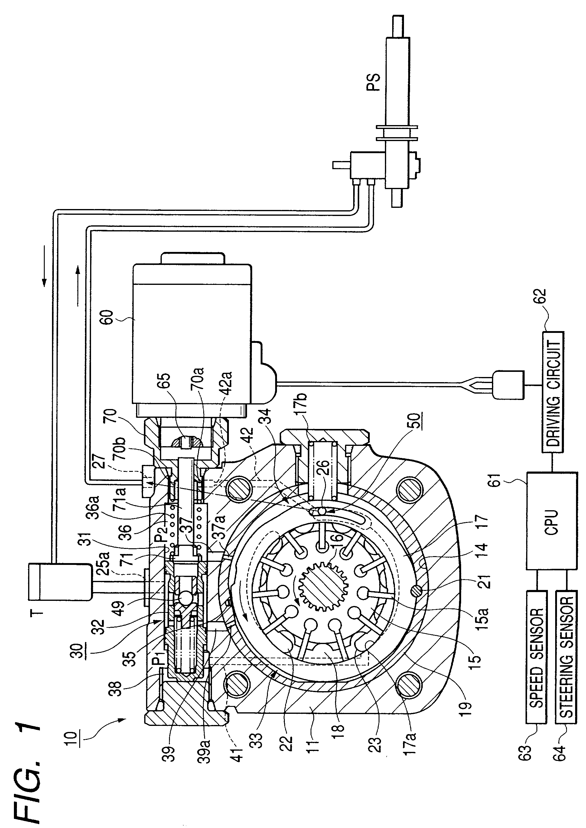
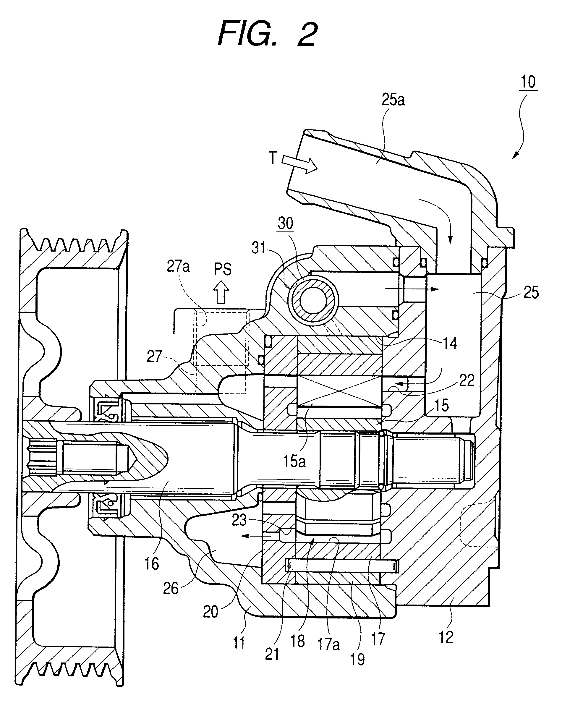
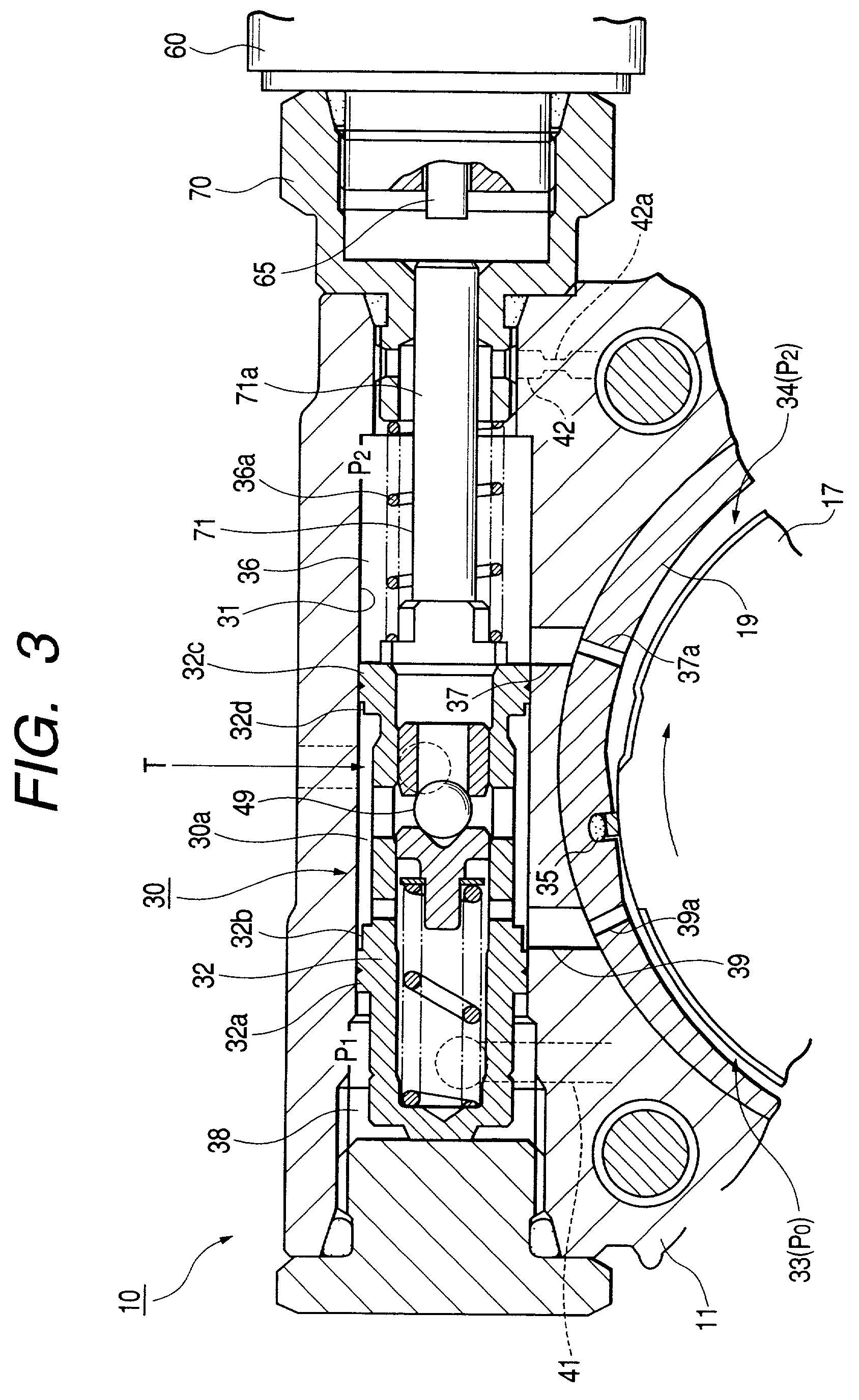
[0030] FIGS. 1 to 3 are views showing an embodiemnt of a variable displacement pump according to the invention. In the embodiment, it is described that the variable displacement pump according to the invention is used for a vane type oil pump of being oil pressure generating source of a power steering system.

[0031] In FIG. 1 and FIG. 2, a vane-type variable displacement pump shown with symbol 10 has a front body 11 and a rear body 12 constructing a pump body. The front body 11 has a cup shape at the whole thereof, a storage space 14 storing and arranging pump composing elements as a pump cartridge is formed at the inside thereof, and the rear body 12 is assembled being combined so as to block the opening end of the storing space 14.

[0032] At the front body 11, a driving shaft 16 to drive to rotate a rotor 15 constructing the pump composing elements from the outside is supported rotatably in the penetrating state. The rotor 15 rotates counterclockwise in FIG. 1.

[0033] Symbol 17 is a ...


PUM


Abstract

A pump chamber 18 is formed between a cam ring 17 and a rotor 15 in a pump body 11. The cam ring is formed so as to move to direction that pump capacity of the pump chamber increases and decreases. A first and second fluid pressure chambers 33 and 34 are formed at both sides of moving direction of the cam ring 17. The pump has a spool operates to axis direction by difference in fluid pressure of upper and lower stream sides of a metering throttle 50 formed on a way of a discharge side passage 27 of the pump chamber and provides at least a control valve 30 controlling fluid pressure in the first fluid pressure chamber. An electronic driving unit applying thrust to axis direction to the spool of the control valve, for example, a solenoid 60 is provided.

Description

[0001] 1. Field of the Invention[0002] The present invention relates to a variable displacement pump used for power steering system (apparatus using pressure fluid) as an oil pressure source (fluid pressure source) to obtain auxiliary steering power lightening the power of steering wheel of vehicle for example.[0003] 2. Description of the Related Art[0004] In the pump used for power steering system, it is desired that pressure fluid of enough quantity to obtain auxiliary steering power corresponding to steering state at steering operation of steering wheel (so called at steering) is applied to a power cylinder of power steering system. Contrary to this, at non-steering such as straight travel of vehicle, supplying the pressure fluid is actually needless.[0005] Moreover, in the pump used for power steering system, it is desired that supplying quantity of pressure fluid at high speed travel is less than at middle or low speed travel and travel stability at high speed straight travel i...

Claims


Application Information

Patent Timeline
Patent Type & Authority Applications(United States)
IPC IPC(8): B62D6/00B62D5/07F04B1/06F04B49/00F04C14/00F04C14/22F04C14/24F04C15/06
CPCF04C14/226F04C2/344F04C14/10F04C15/06
Inventor KONISHI, HIDEO
Owner HITACHI AUTOMOTIVE SYST STEERING
Why Eureka
Try Eureka