Injection control method of die-casting machine and injection control unit of die-casting machine

a technology of injection control unit and die-casting machine, which is applied in the direction of electric/magnetic/electromagnetic heating, manufacturing tools, instruments, etc., can solve the problems of difficult control of the whole injection operation, decreased work efficiency, and difficulty in executing control over the whole injection operation

Inactive Publication Date: 2001-11-22
TOSHIBA MASCH CO LTD
View PDF5 Cites 11 Cited by
  • Summary
  • Abstract
  • Description
  • Claims
  • Application Information

AI Technical Summary

Benefits of technology

[0017] In this case, by first performing the operation by the ordinary injection position feedback control, special preparations necessary for the calculation of correction value of the present invention or the like can be avoided. Also, by using the previous data obtained during the operation by injection position feedback control, the control is shifted to the open loop control of injection velocity for the next shot, so that the operation control based on the calculation of correction value in accordance with the present invention can be carried out.
[0022] In this case, a shift between the detected velocity data and the target velocity data due to servo delay can be compensated more reliably, so that a more exact correction value can be obtained.
[0024] In this case, the user can perform programming with the injection waveform pattern in terms of position and velocity in mind. Such an injection waveform pattern in terms of position and velocity has conventionally been general for a die-casting machine and easily understood by the operator. Therefore, by deriving various types of data necessary for the present invention from the injection waveform pattern in terms of position and velocity, the ease of user setting can be increased, and the handling performance can be improved further.

Problems solved by technology

Therefore, if control of various operational conditions is carried out manually, a satisfactory result cannot be obtained, and also the work efficiency is decreased.
In the above-described control method for a die-casting machine, although a high-velocity injection operation and a low-velocity injection operation are controlled, it is difficult to carry out control over the whole section of injection operation.
Also, since there is gate resistance depending on mold characteristics, it is not easy to issue a velocity command to be executed by open loop control of injection velocity from the beginning.
Specifically, a slight servo delay is inevitable in a servo system for the injection cylinder unit.
If the servo delay becomes remarkable, the detected velocity data and the target velocity data, which are compared with each other, do not correspond correctly to each other, so that a proper correction value cannot be obtained.

Method used


Image

  • Injection control method of die-casting machine and injection control unit of die-casting machine
  • Injection control method of die-casting machine and injection control unit of die-casting machine
  • Injection control method of die-casting machine and injection control unit of die-casting machine

Examples


Embodiment Construction

)

[0037] One embodiment of the present invention will now be described with reference to the accompanying drawings.

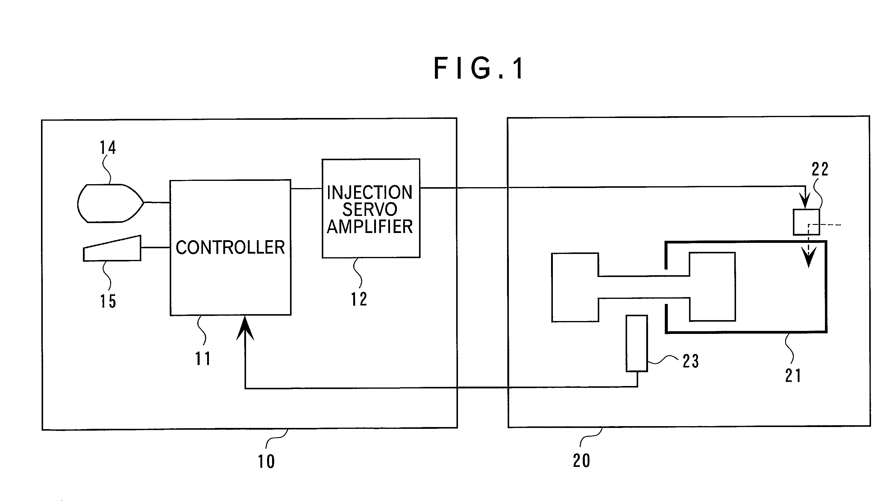
[0038] In FIG. 1, a control unit 10 for a die-casting machine controls the injection operation of a die-casting machine 20. The control unit 10 has a controller 11 using a computer system such as a numerical control system (NC system).

[0039] The controller 11 is connected with a display 14 for generating displays and a keyboard 15 for operation. As necessary, an input device such as a mouse is added. The controller 11 is connected with an injection servo amplifier 12, and the output of the injection servo amplifier 12 is connected to the die-casting machine 20.

[0040] The die-casting machine 20 has an injection cylinder unit 21 provided with an injection servo valve 22 for controlling hydraulic oil introduced into the machine. The output of the injection servo amplifier 12 is connected to the injection servo valve 22. By the opening / closing of the injection servo valve 22...


PUM

PropertyMeasurementUnit
velocityaaaaaaaaaa
timeaaaaaaaaaa
injection velocityaaaaaaaaaa

Abstract

Target velocity data D14 specifying injection operation required for a injection cylinder unit is set in advance, the injection operation is performed actually, command data D17 given to the injection cylinder unit during the injection operation and detected velocity data D15 indicating the operation performed by the injection cylinder unit are recorded, correction value data D18 is calculated from a difference between the detected velocity data D15 and the target velocity data D14 to correct the command data D17 of the previous injection operation by using the correction value, auxiliary amplifier command data D19 is generated as the command data for the next injection operation, and the injection cylinder unit is operated by giving the generated auxiliary amplifier command data at the time of the next injection operation.

Description

[0001] 1. Field of the Invention[0002] The present invention relates to an injection control method and an injection control unit for a die-casting machine, more particularly, which can be used for injection control of a die-casting machine in which an injection velocity is controlled to turn out high-quality die cast products.[0003] 2. Description of Related Art[0004] It has so far been known that the quality of a die cast product is greatly influenced by an injection velocity and an injection pressure when melt is charged into a mold. Therefore, various considerations are given to the control of these velocity and pressure.[0005] For example, in injecting melt into the mold by using an injection cylinder unit, a procedure is used in which an injection plunger is first advanced at a low velocity so as to prevent melt in a passage from bubbling, and when the front end of melt reaches the interior of the mold, the advance velocity is switched to a high velocity to charge the melt int...

Claims


Application Information

Patent Timeline
Patent Type & Authority Applications(United States)
IPC IPC(8): B22D17/32B29C45/76B29C45/77
CPCB22D17/32B29C45/76B29C45/77B29C2945/76083B29C2945/7611B29C2945/76204B29C2945/76568B29C2945/76595B29C2945/76682B29C2945/76785B29C2945/76933B29C2945/76943
Inventor YOKOYAMA, HIROSHIKANEKO, YUJI
Owner TOSHIBA MASCH CO LTD
Why Eureka
Try Eureka