Oscillating circuit

a technology of oscillating circuit and oscillating frequency, which is applied in the direction of oscillating generator, pulse automatic control, pulse technique, etc., can solve the problems of inability to accurately regulate and the regulation of the vco oscillating frequency takes a great deal of time and labor, so as to improve the drift speed, the effect of stabilizing the value of the parasitic capacity and increasing the speed of the change of the electric potential

Inactive Publication Date: 2001-12-13
SEMICON COMPONENTS IND LLC
View PDF0 Cites 5 Cited by
  • Summary
  • Abstract
  • Description
  • Claims
  • Application Information

AI Technical Summary

Benefits of technology

[0009] In consideration of the problems, the invention is intended for fixing an electric potential of an epitaxial layer provided under a bonding pad to which a resonance circuit for a VCO is connected to a predetermined electric potential through a resistor, thereby increasing a speed of a change in the electric potential of the epitaxial layer and quickly stabilizing a value of a parasitic capacity, resulting in an improvement in a drift when a power supply is turned ON.

Problems solved by technology

For this reason, when a VCO coil is to be varied and regulated to generate a desirable AFT voltage, a VCO oscillating frequency cannot be regulated accurately or the regulation takes a great deal of time and labor if a drift is caused while the IC power is ON.

Method used


Image

  • Oscillating circuit
  • Oscillating circuit
  • Oscillating circuit

Examples


Embodiment Construction

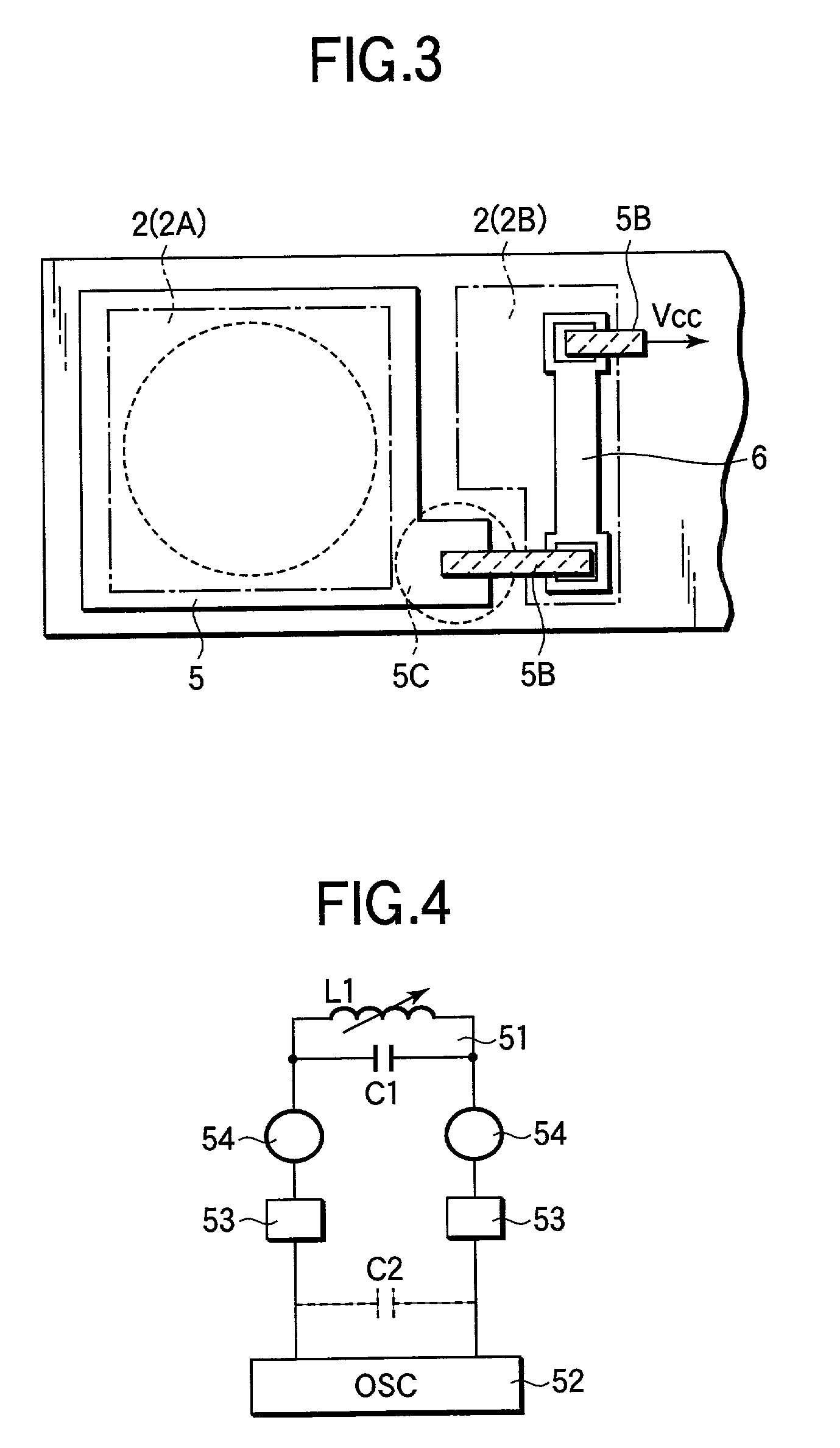
[0020] A video signal receiving circuit according to an embodiment to which an oscillating circuit of the invention is applied will be described below with reference to the drawings. Since a basic circuit structure of the video signal receiving circuit is equivalent to the circuit structure shown in FIG. 4, description thereof will be omitted to avoid repetitive explanation.

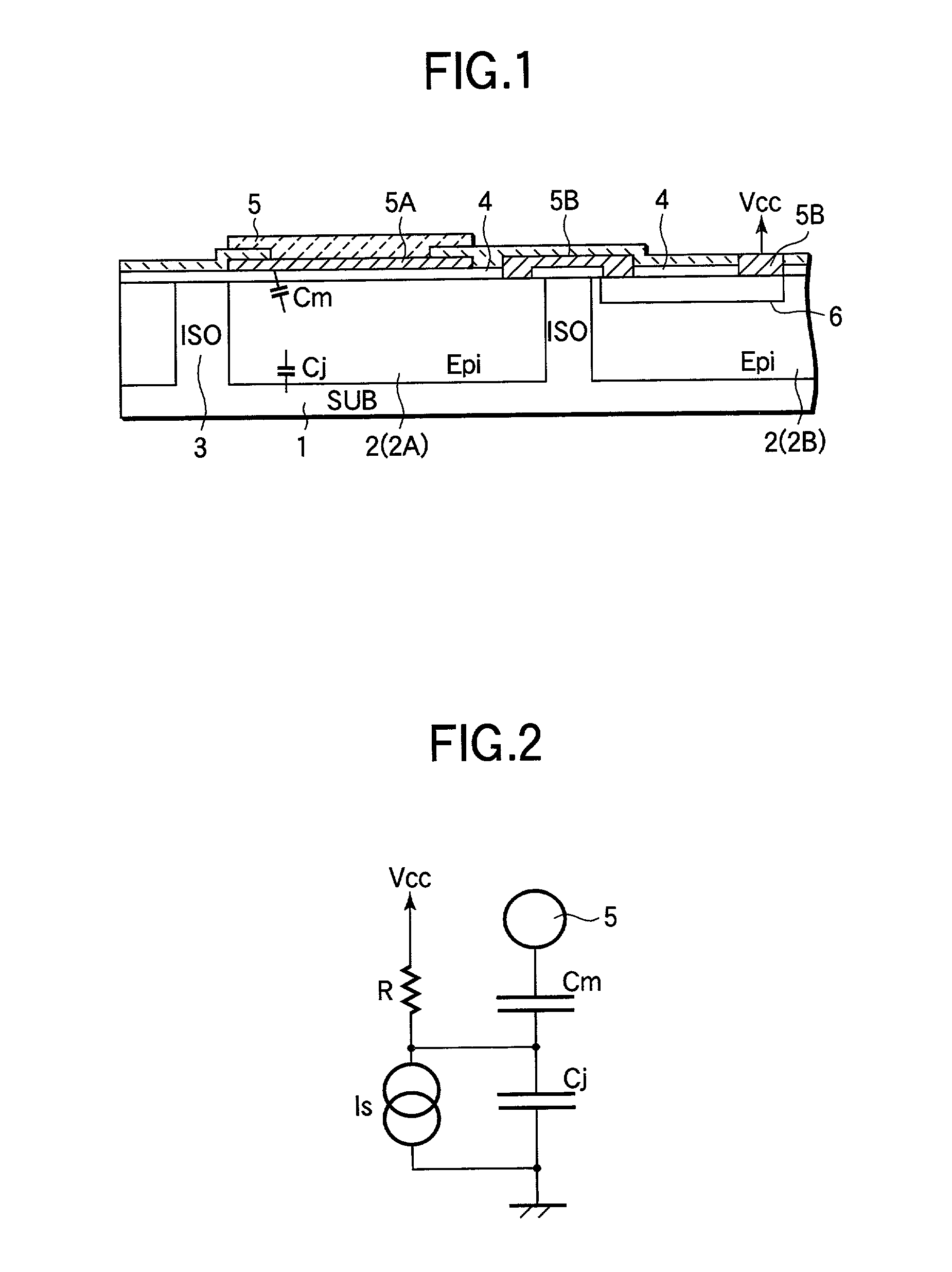
[0021] FIGS. 1 and 3 are sectional and plan views showing a bonding pad structure in the oscillating circuit according to the invention.

[0022] In FIGS. 1 and 3, the reference numeral 1 denotes a P-type semiconductor substrate, for example, and the reference numeral 2 denotes an island formed in the substrate 1 (which will be hereinafter referred to as an N-type epitaxial layer 2). Each epitaxial layer 2 is isolated through an element isolating region (ISO) 3.

[0023] The reference numeral 4 denotes an oxide film formed on the substrate 1, and a bonding pad 5 formed of a metal layer is provided on the epitaxial laye...


PUM


Abstract

An electric potential of an epitaxial layer 2A provided under a bonding pad 5 to which a resonance circuit for a VCO is to be connected is fixed to a predetermined (Vcc) electric potential through a resistor 6 in a conventional floating state. Consequently, a speed of a change in the electric potential of the epitaxial layer 2A is increased and a value of a parasitic capacity is stabilized quickly. Consequently, a drift can be improved when a power supply is turned ON.

Description

BACKGROUND OF THE INVENTION[0001] The present invention relates to an oscillating circuit, and particularly, to an oscillating circuit to be used for a video signal receiving device having an improved VCO (voltage controlled oscillator) free run frequency characteristic, particularly, which serves to detect a video in a PLL (phase-locked loop) type video detecting circuit, for example.[0002] In the PLL type video detecting circuit, a VCO circuit for locking to an input signal to detect a video is used. The VCO circuit regulates a free run frequency into an IF frequency (for example, 45.75 MHz specified for U.S.) to be used by means of an externally provided resonance circuit 51 formed by a variable coil L1 and a capacitor C1 as shown in FIG. 4. The resonance circuit 51 is connected to an oscillator 52 provided in an IC through an IC pin 54 of a lead frame (not shown) and a bonding pad 53 for connecting with an IC terminal. The resonance circuit may be constituted by an internal elem...

Claims


Application Information

Patent Timeline
Patent Type & Authority Applications(United States)
IPC IPC(8): H01L27/04H01L21/822H03B5/04H03B5/12
CPCH03B5/04H03B5/00
Inventor CHIGIRA, HIROKAZUOKUMURA, MASAOKOYANAGI, TATSUROMASHIMO, NAOSHISAITO, TOMOYUKIOSAWA, MITSUOHAYAKAWA, NOBUKAZUKUBO, KOUKI
Owner SEMICON COMPONENTS IND LLC
Why Eureka
Try Eureka