Method and apparatus for assembling a three-dimensional structural component

a three-dimensional structural and component technology, applied in the direction of fuselages, manufacturing tools, transportation and packaging, etc., can solve the problems of inability to adjust the individual subassemblies in order to ensure the desired overall geometry of the aircraft fuselage, inability to correct, and possible positional deviations of the floor structure relative to the fuselage body. achieve the effect of increasing the accessibility of tools and precise tolerance ranges

Inactive Publication Date: 2001-12-27
AIRBUS OPERATIONS GMBH
View PDF0 Cites 82 Cited by
  • Summary
  • Abstract
  • Description
  • Claims
  • Application Information

AI Technical Summary

Benefits of technology

0009] to provide an assembly method and apparatus for producing large scale components such as jumbo aircraft bodies, whereby the assembly permits maintaining required, precise tolerance ranges without the need for high precision jigs and without drilling precisely positioned locating holes, while still assuring the accuracy of the three-dimensional large scale body;
0010] to substantially increase the accessibility of tool...

Problems solved by technology

Such a zero alignment system has the disadvantages that the zero alignment can result in deviations, particularly along the interface between individually neighboring subassemblies.
Moreover, an adjusting of the individu...

Method used


Image

  • Method and apparatus for assembling a three-dimensional structural component
  • Method and apparatus for assembling a three-dimensional structural component
  • Method and apparatus for assembling a three-dimensional structural component

Examples


Embodiment Construction

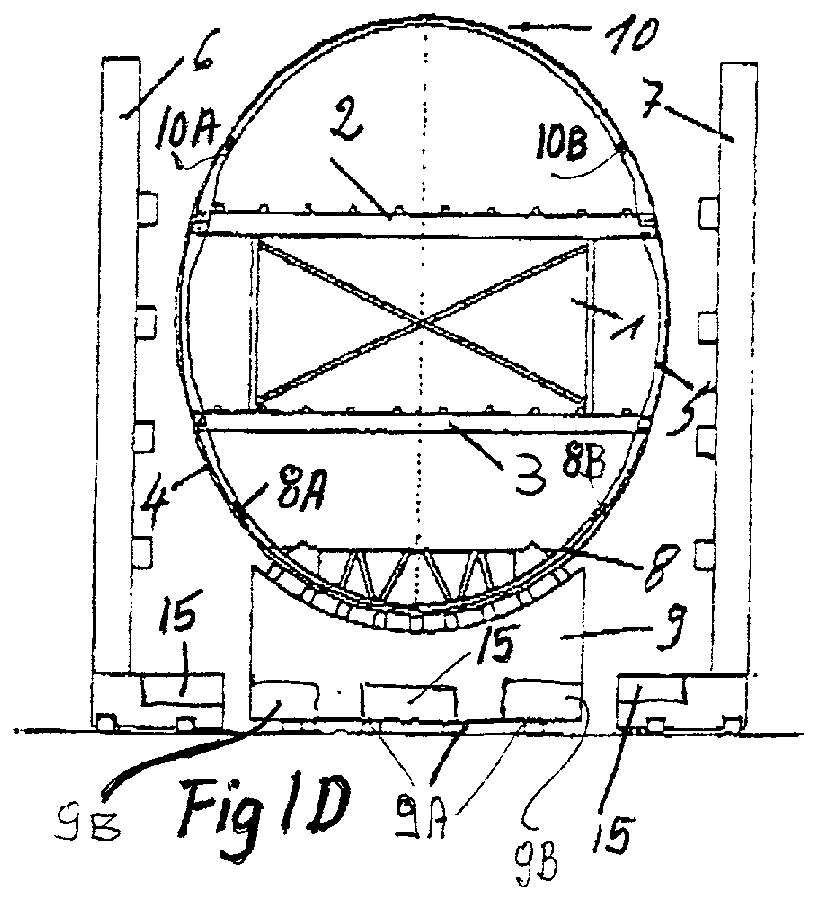
[0021] FIG. 1A illustrates the first stage in which a central longitudinal assembly core 1 is secured with its far end to a mounting 12 forming part of a mounting column 12A. The opposite end of the core 1 is held in place by a further mounting part 13 of a mounting column 13A to be described below with reference to FIG. 2. The central axis of the assembly core 1 extends in the direction of the central longitudinal axis of an aircraft fuselage not shown in FIG. 1. Preferably, the assembly core 1 has a rectangular cross-section. An upper floor grid 2 and a lower floor grid 3 are mechanically secured in a releasable manner by symbolically shown clamping tools 16 driven by clamp drives 16A which in turn are controlled by a computer 17. A laser distance measuring system 18 is positioned for measuring any deviation of the core 1 from standard dimensions stored in the memory of the computer 17. The clamping tools 16 are adjustable by the clamp drives 16A in the Z-direction of the aircraft...


PUM

PropertyMeasurementUnit
Electric chargeaaaaaaaaaa
Currentaaaaaaaaaa

Abstract

Three-dimensional large scale bodies such as jumbo aircraft fuselages (14) are assembled in body sections around a central longitudinal assembly core (1) which itself is mounted at its ends and accessible all around along its length. Robots carrying tools for holding, transporting and precisely positioning preassembled wall shell sections, are movable along the central core (1). First, at least one floor grid (2 or 3) is releasably mounted to the core. Then, side wall shell sections (4, 5) are secured to the floor grids. Then, top and bottom wall shell sections (10, 8) are secured to the side wall shell sections (4, 5) to form a body section (BS) of the large scale body (14). Neighboring body sections are secured to each other along cross-seams. Upon completion, the floor grids are released from the core (1) and the core is removed preferably withdrawn longitudinally from the assembled large component or body.

Description

PRIORITY CLAIM[0001] This application is based on and claims the priority under 35 U.S.C. .sctn.119 of German Patent Application 199 29 471.2, filed on Jun. 26, 1999, the entire disclosure of which is incorporated herein by reference.[0002] The invention relates to a method and an apparatus for producing large three-dimensional structural components such as an aircraft fuselage or the like having a barrel-shaped configuration or an oval or circular cross-section.BACKGROUND INFORMATION[0003] So-called large volume or jumbo aircraft have fuselages assembled from shell sections, preferably shell sections reinforced by load supporting elements such as stringers and spars or ribs. One or more plate-shaped floor grids are mounted inside such large scale fuselages. The floor grids extend longitudinally inside the fuselage and from one side wall to the opposite side wall.[0004] German Patent Publication DE 34 38 584 A1 discloses an apparatus for the manufacture of an aircraft fuselage, wher...

Claims


Application Information

Patent Timeline
IPC IPC(8): B21J15/10B23P19/04B64C1/00B64C1/06B64F5/00B64F5/10
CPCB21J15/10Y10T29/53004B23P19/04B23P2700/01B64C1/068B64C2001/0027B64F5/0009Y10T29/49904Y10T29/4981Y10T29/4978Y10T29/53957Y10T29/49622Y10T29/53313Y10T29/49778Y10T29/5177Y10T29/53091Y10T29/49998Y10T29/49899Y10T29/49901Y10T29/53961Y10T29/53061B21J15/142B64F5/10
Inventor LEHMKER, JOACHIMMUEHLNICKEL, KARL-HEINZSTOEWER, UDO-HENNINGVOLLMERHAUS, RUEDIGER
Owner AIRBUS OPERATIONS GMBH
Why Eureka
Try Eureka