Broadcasting receiving apparatus

a technology of receiving apparatus and broadcasting, which is applied in the direction of diversity/multi-antenna system, polarisation/directional diversity, individually energised antenna array, etc., and can solve the problems of system itself becoming complicated, unfavorable optimal control, and higher system cos

Inactive Publication Date: 2001-12-27
TDK CORPARATION
View PDF7 Cites 41 Cited by
  • Summary
  • Abstract
  • Description
  • Claims
  • Application Information

AI Technical Summary

Problems solved by technology

In case of such a prior system, if the GPS receiving is not available, an optimum control is not possible.
Such a system is higher cost.
However, when considering public applications, the

Method used


Image

  • Broadcasting receiving apparatus
  • Broadcasting receiving apparatus
  • Broadcasting receiving apparatus

Examples


Embodiment Construction

[0033] Genera Construction

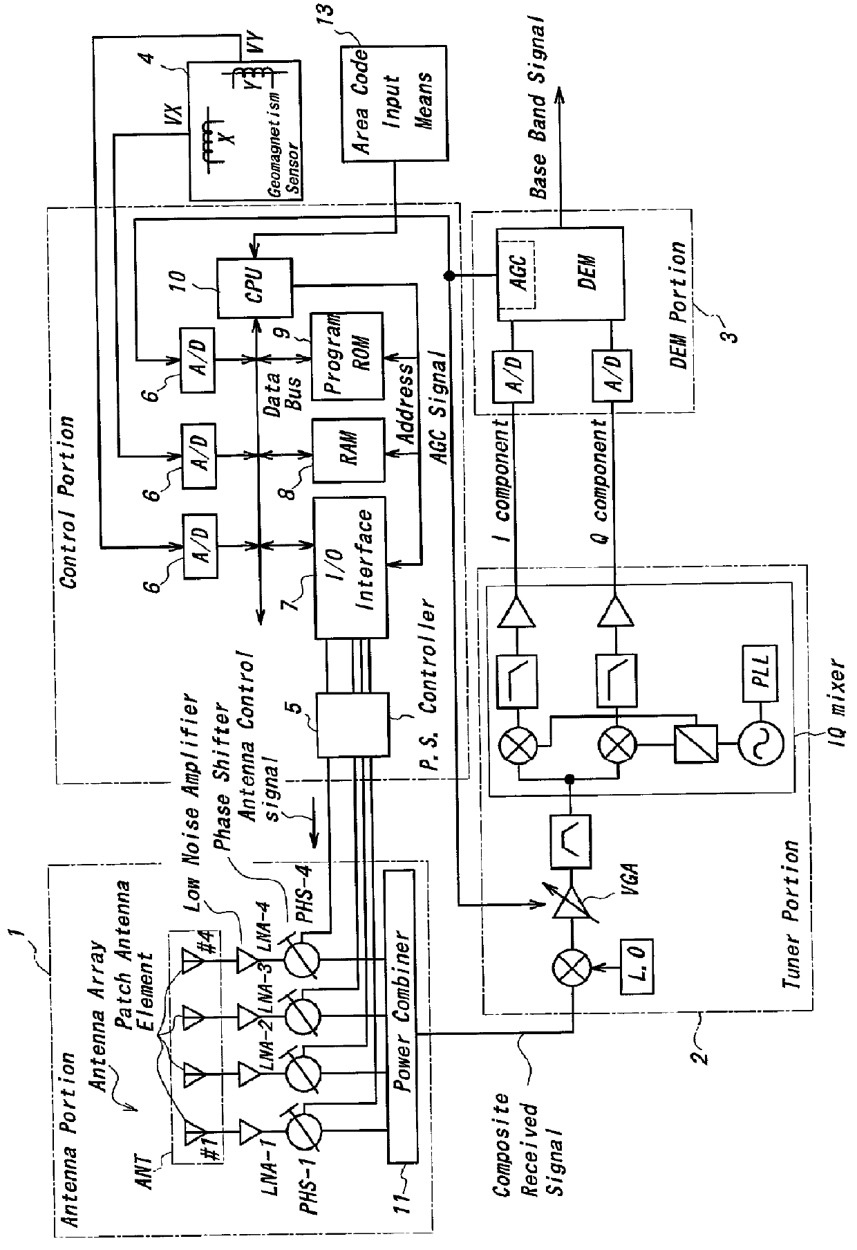
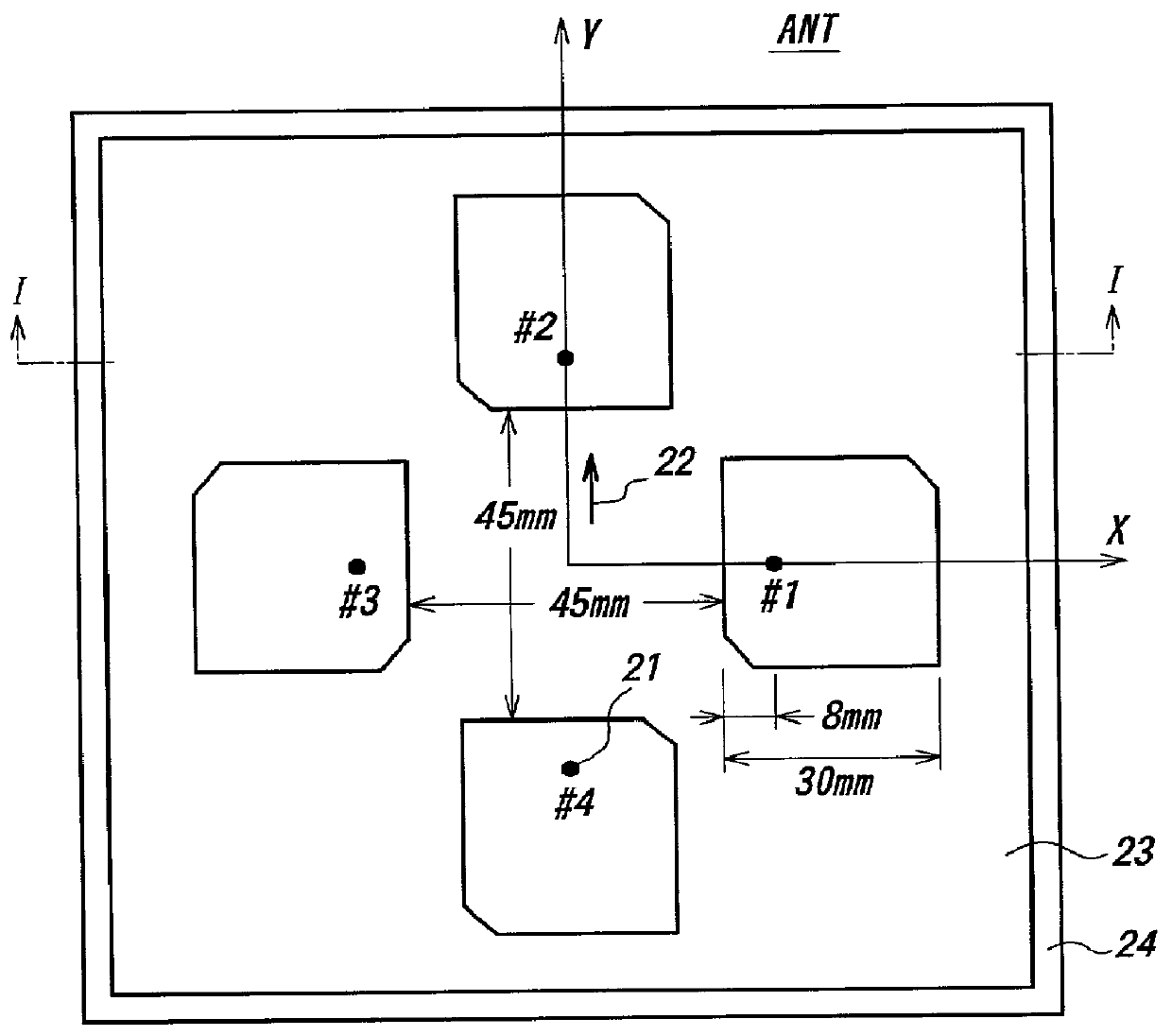
[0034] FIG. 1 shows a block diagram of one embodiment of the signal receiving apparatus made in accordance with the present invention. The receiving device of this embodiment is a device for receiving a base band signal modulated by QPSK or BPSK modulation system. Although the device will be explained here as to receive a signal of QPSK or BPSK modulation, but the invention is not limited to such a modulation system. The base band signal is a digital signal obtained by coding an analog signal such as a music and having a transmission error check function. The frequency of the carrier wave is in the S-band, for instance, 2.6 GHz. The antenna array ANT in the antenna portion 1 comprises 4 patch antenna elements #1-#4 each consisting of a microstrip patch antenna. The signal received by respective patch antenna element is amplified by respective one of low noise amplifiers LNA1-LNA4 and than passing through respective one of phase shifters PHS1-PHS4 and then c...


PUM


Abstract

Receiving apparatus for receiving satellite broadcasting electric wave to be mounted mobile vehicle being realized at low cost and not influence by the weather etc. The apparatus is provided with an antenna of which directivity pattern can be varied, and by a geomagnetism sensor mechanically coupled with said antenna to detect present orientation of the antenna, and comprising antenna controlling means by which the directivity pattern of the antenna is directed towards objective broadcasting satellite based on said detected orientation output. When an electric wave from a gap-filler station is to be received, the antenna is controlled to become non-directivity pattern automatically. For the antenna, a microstrip patch antenna having a plurality of conductive patches arranged in a plane is used.

Description

[0001] 1. Field of the Invention[0002] The present invention generally relates to a signal receiving apparatus mainly mounted on a mobile vehicle but may include a stationary or mobile receiving site from a signal sent from a satellite and from a ground transmitter station. More especially, the invention relates to a signal receiving apparatus able to optimize the receiving signal intensity by varying the directivity of the antenna according to the receiving location and the receiving conditions so as to receive a stabilized signal even if the receiving conditions vary.[0003] 2. Prior Art Description[0004] Presently planned S-band mobile multimedia satellite broadcasting system is to use a stationary communication satellite with S-band frequencies i.e. 2.6 GHz band to transmit information contents relating to data or text, voice and moving pictures etc. to a mobile apparatus. The system is to realize a communication link without the need to track the satellite wave by using a parabo...

Claims


Application Information

Patent Timeline
IPC IPC(8): H01Q1/38H01Q3/26H01Q3/30H01Q21/06H04B7/08H04B7/10H04B7/185H04B7/26
CPCH01Q1/38H01Q3/26H01Q3/30H01Q21/065H04B7/18517
Inventor IKEDA, MASAAKISATO, NORIAKINAKAMURA, TOSHIHISA
Owner TDK CORPARATION
Why Eureka
Try Eureka