Numerically controlled curved surface machining unit

a machining unit and numerical control technology, applied in the direction of program control, electric programme control, instruments, etc., can solve the problems of large amount of nc data at shorter pitches, poor roughness and a lot of hand-finishing steps, etc., to improve the accuracy of the machining surface. , the effect of improving the accuracy of the machining surfa

Inactive Publication Date: 2002-01-03
HITACHI SOFTWARE ENG +1
View PDF0 Cites 49 Cited by
  • Summary
  • Abstract
  • Description
  • Claims
  • Application Information

AI Technical Summary

Problems solved by technology

In the conventional numerically controlled (NC) curved surface machining, since a workpiece is machined by linear approximation as shown in FIG. 2(a), the machining surface roughness is poor and a lot of hand-finishing steps are needed.
Besides, as shown in FIG. 2(b), since an average feed rate decreases as a result of acceleration or deceleration in positioning, long machining time is needed and, what is worse, there lies a problem that a vast amount of NC data at shorter pitches are required to improve the machining surface accuracy.
Even with this conventional method, however, there still lies a problem of poor machining surface roughness due to linear approximation and lower average feed rate due to acceleration or deceleration in positioning.
Since the chord length between the knot vectors is uniform in this machining method, there lies a problem that less consideration is given to the control of a curve using the knot vector, which is a characteristic feature of a NURBS curve.
Generally speaking, however, there is no guarantee of achieving a smooth curve even if the same knot vector is employed after the coordinate transformation.
In addition, this prior art handles ball end mill machining where the offset of a contact point between the tool control point and the curved surface is small, and does not handle radius end mill machining where the offset of a contact point between the tool control point and the curved surface is big.
Because of this, there remains a high possibility that wind or warp is caused depending upon the extent of the offset.

Method used


Image

  • Numerically controlled curved surface machining unit
  • Numerically controlled curved surface machining unit
  • Numerically controlled curved surface machining unit

Examples


Embodiment Construction

[0080] Preferred embodiments of a numerically controlled curved surface machining unit according to the present invention are described hereunder, using FIG. 1 through FIG. 17.

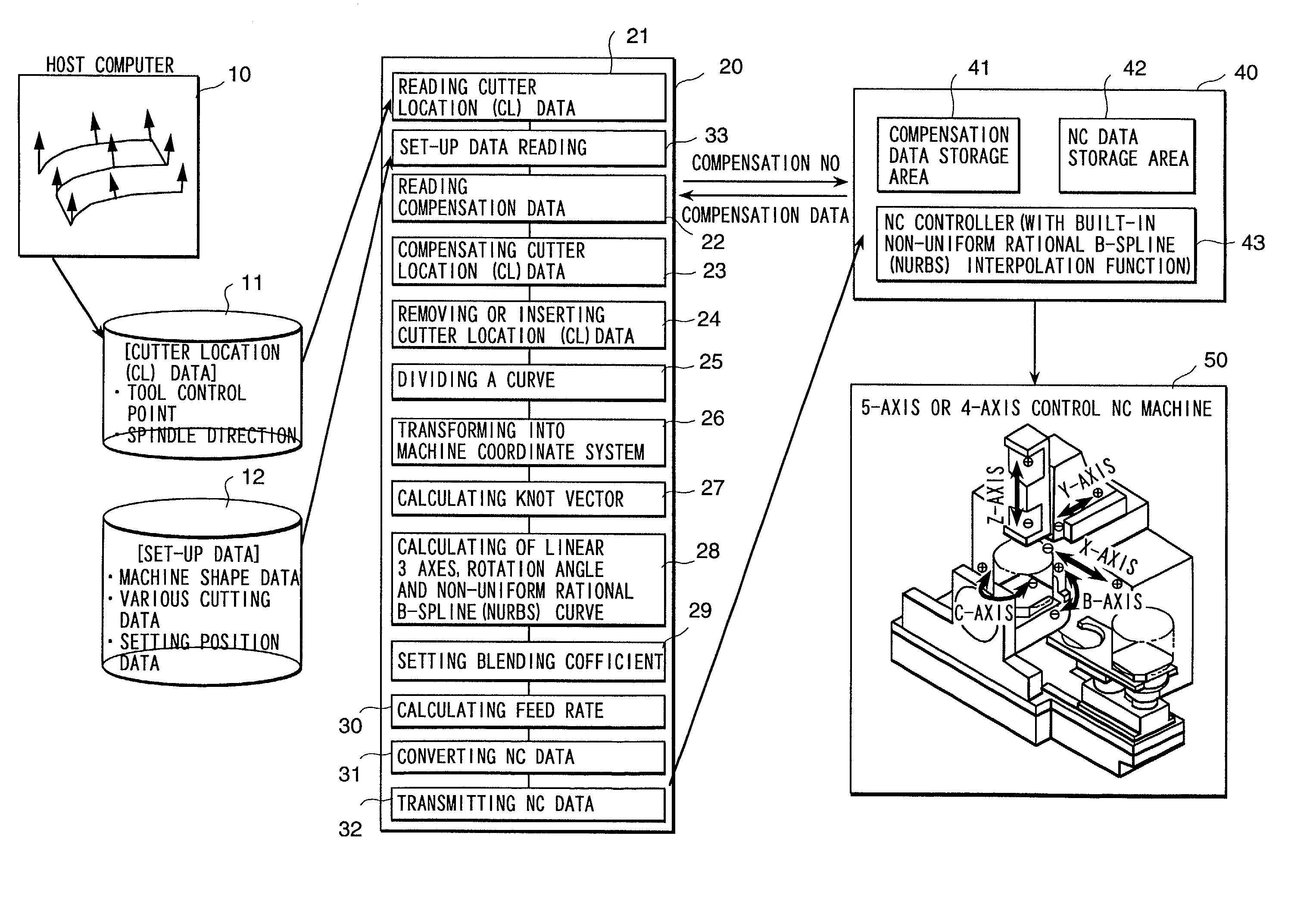
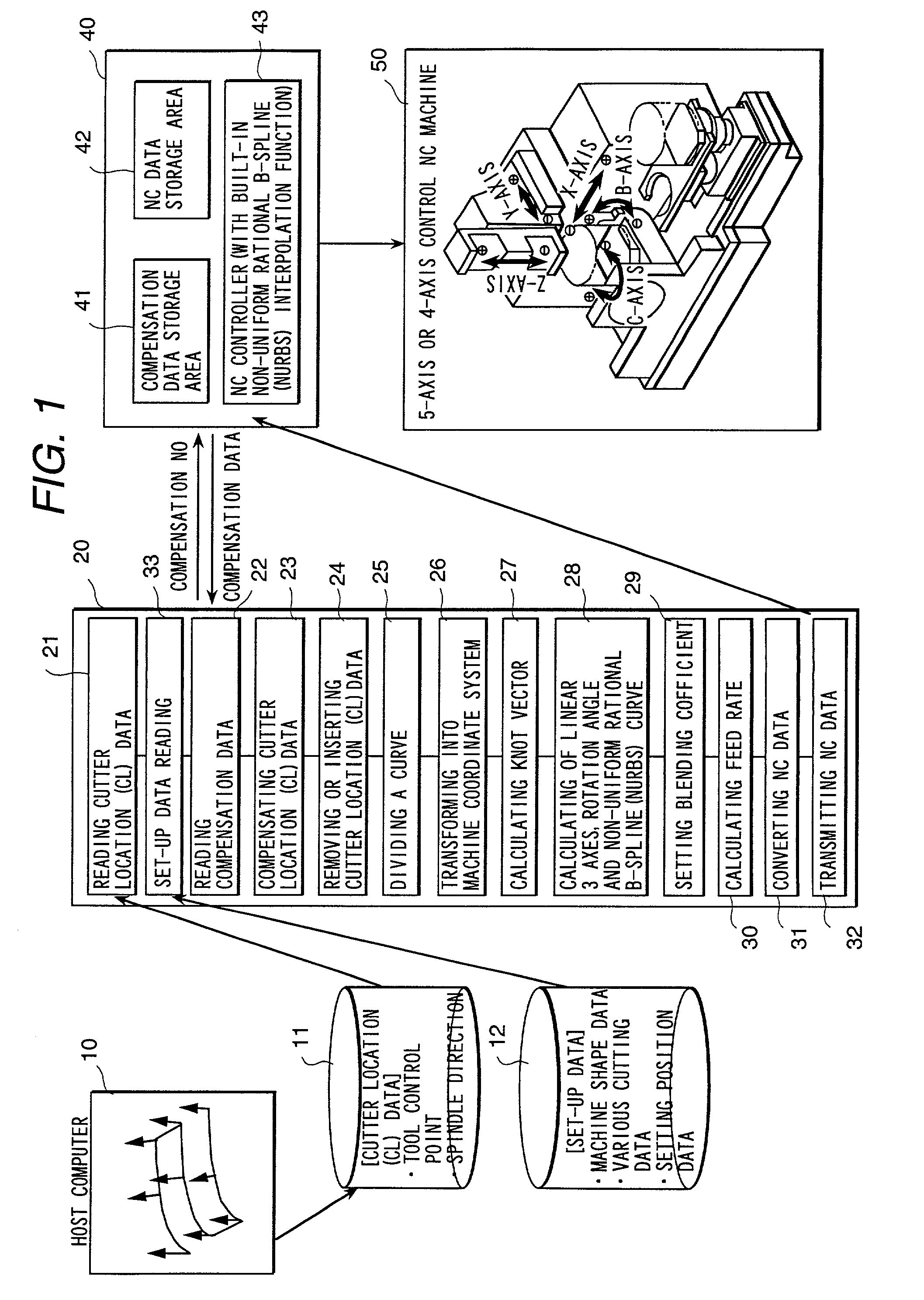
[0081] FIG. 1 is a block diagram showing the whole configuration of an embodiment of the numerically controlled curved surface machining unit according to the present invention. A host computer 10 stores the tool control point vector and tool axis vector calculated along the tool path on a coordinate system with defined curved shape (workpiece coordinate system) in an external file 11 as cutter location (CL) data.

[0082] In step 21, a computer 20 of the numerically controlled curved surface machining unit reads CL data from the external file 11. Instep 33, the computer reads set-up data necessary for NC data conversion, including machine shape data, cutting specification data, setting position data, from an external file 12.

[0083] There is always an error between the supposed tool length or tool diameter in pre...


PUM


Abstract

To provide a numerically controlled curved surface machining unit, and a method or program thereof, which, by moving a tool smoothly along a NURBS (non-uniform rational B-spline) curve, enables not only to improve the machining surface roughness and machining surface accuracy but to achieve high-speed machining so as to be able to eliminate hand finishing and reduce machining steps drastically. Performing NURBS (non-uniform rational B-spline) interpolation machining by a machine equipped with a means for reading cutter location (CL) data consisting of a tool control point vector and a tool axis vector on a workpiece coordinate system, a means for converting the CL data into a position vector of three linear axes and a rotation angle on a machine coordinate system in accordance with the machine configuration of a simultaneous multiple-axis NC machine, a means for calculating knot vectors of a NURBS curve with the most suitable chord length on the basis of a position vector of the three linear axes and a rotation angle, a means for calculating NURBS curve of the three linear axes and one rotary axis using the knot vectors, a means for converting the NURBS curve into NURBS interpolation NC data, a means for converting the feed rate on a workpiece coordinate system into the feed rate per minute on a machine coordinate system, and a means for transmitting NC data to a NC machine.

Description

[0001] 1. Field of Utilization in Industry[0002] The present invention relates to a numerically controlled curved surface machining unit, particularly to such a unit that improves machining surface roughness and accuracy and enables to achieve high-speed machining.[0003] 2. Description of Prior Art[0004] In the conventional numerically controlled (NC) curved surface machining, since a workpiece is machined by linear approximation as shown in FIG. 2(a), the machining surface roughness is poor and a lot of hand-finishing steps are needed. Besides, as shown in FIG. 2(b), since an average feed rate decreases as a result of acceleration or deceleration in positioning, long machining time is needed and, what is worse, there lies a problem that a vast amount of NC data at shorter pitches are required to improve the machining surface accuracy.[0005] Japanese Application Patent Laid-Open Publication No. HEI 9-114512 (1997) proposes a method of curved surface machining by a NC machine tool fo...

Claims


Application Information

Patent Timeline
Patent Type & Authority Applications(United States)
IPC IPC(8): G05B19/4103B23Q15/00G05B19/4099
CPCG05B19/4099G05B2219/34141
Inventor HIRAI, JUNICHIARAI, HIROSHIHARIHARA, TAMOTSUCHIBA, OSAMUTAKAHASHI, MASAAKIKANAMARU, NOBUHISA
Owner HITACHI SOFTWARE ENG
Why Eureka
Try Eureka