In-cylinder injection type spark-ignition internal combustion engine and method

a technology of internal combustion engine and injection cylinder, which is applied in the direction of machines/engines, electrical control, mechanical equipment, etc., can solve the problems of insufficient fuel pressure failure to realize the desired engine start-up, and insufficient pressure of the fuel in the accumulator at the start-up of the engine, so as to reduce the engine output and reduce the engine output. the effect of the engine output and the effect of reducing th

Inactive Publication Date: 2002-01-10
TOYOTA JIDOSHA KK
View PDF0 Cites 2 Cited by
  • Summary
  • Abstract
  • Description
  • Claims
  • Application Information

AI Technical Summary

Benefits of technology

[0008] It is therefore an object of the invention to provide an in-cylinder injection type spark-ignition internal combustion engine and method of operating same which makes it possible to perform favorable engine start-up, and to warm up the catalyst device in the engine exhaust system without decreasing the engine output.
[0009] To accomplish the above and / or other objects, a first aspect of the invention provides an in-cylinder injection spark-ignition internal combustion engine including a plurality of cylinders and a catalyst device disposed in an exhaust system of the engine, in which a fuel is injected to at least one selected cylinder selected from the plurality of cylinders to be operated, and subsequently the fuel is injected to all cylinders to be operated. A variable of warm-up control to the catalyst device for the selected cylinder is smaller than that used when all cylinders are operated. In the engine according to the first aspect of the invention, the warm-up control of the catalyst device in the engine exhaust system is conducted at the engine start-up at a relatively earlier stage. Further, the warm-up controlled variable is kept to a small value during operation of the selected cylinder. This is effective to restrict the decrease in the engine output, thus providing favorable start-up of the engine.
[0010] In an in-cylinder injection spark-ignition internal combustion engine including a plurality of cylinders and a catalyst device disposed in an exhaust system of the engine, a fuel is injected to at least one selected cylinder selected from the plurality of cylinders to be operated, and subsequently the fuel is injected to all cylinders to be operated. According to a second aspect of the invention, the all cylinder operation is started and the warm-up control is started for all cylinders to warm up the catalyst device disposed in the exhaust system of the engine when a fuel injection pressure exceeds a target value. In the engine according to the second aspect of the invention, the warm-up control of the catalyst device in the engine exhaust system is not conducted during operation of the selected cylinder. This is effective to restrict the decrease in the engine output, thus providing favorable start-up of the engine. Additionally, this may realize reliable fuel injection at a high pressure while operating all cylinders with a reduced discharge amount of harmful materials.

Problems solved by technology

However, the high-pressure pump does not operate sufficiently at the engine start-up, resulting in insufficient pressurization of the fuel in the accumulator.
However, the fuel pressure in the accumulator at the engine start-up is too low to successively inject an increased amount of the fuel required at the engine start-up into the cylinders.
As a result, the required amount of the fuel cannot be injected to each of the cylinders, causing misfire and failing to realize the desired engine start-up.
However, the foregoing warm-up control may deteriorate the combustion condition.
The small increase in the engine speed may deteriorate the engine start-up performance.

Method used


Image

  • In-cylinder injection type spark-ignition internal combustion engine and method
  • In-cylinder injection type spark-ignition internal combustion engine and method
  • In-cylinder injection type spark-ignition internal combustion engine and method

Examples


Embodiment Construction

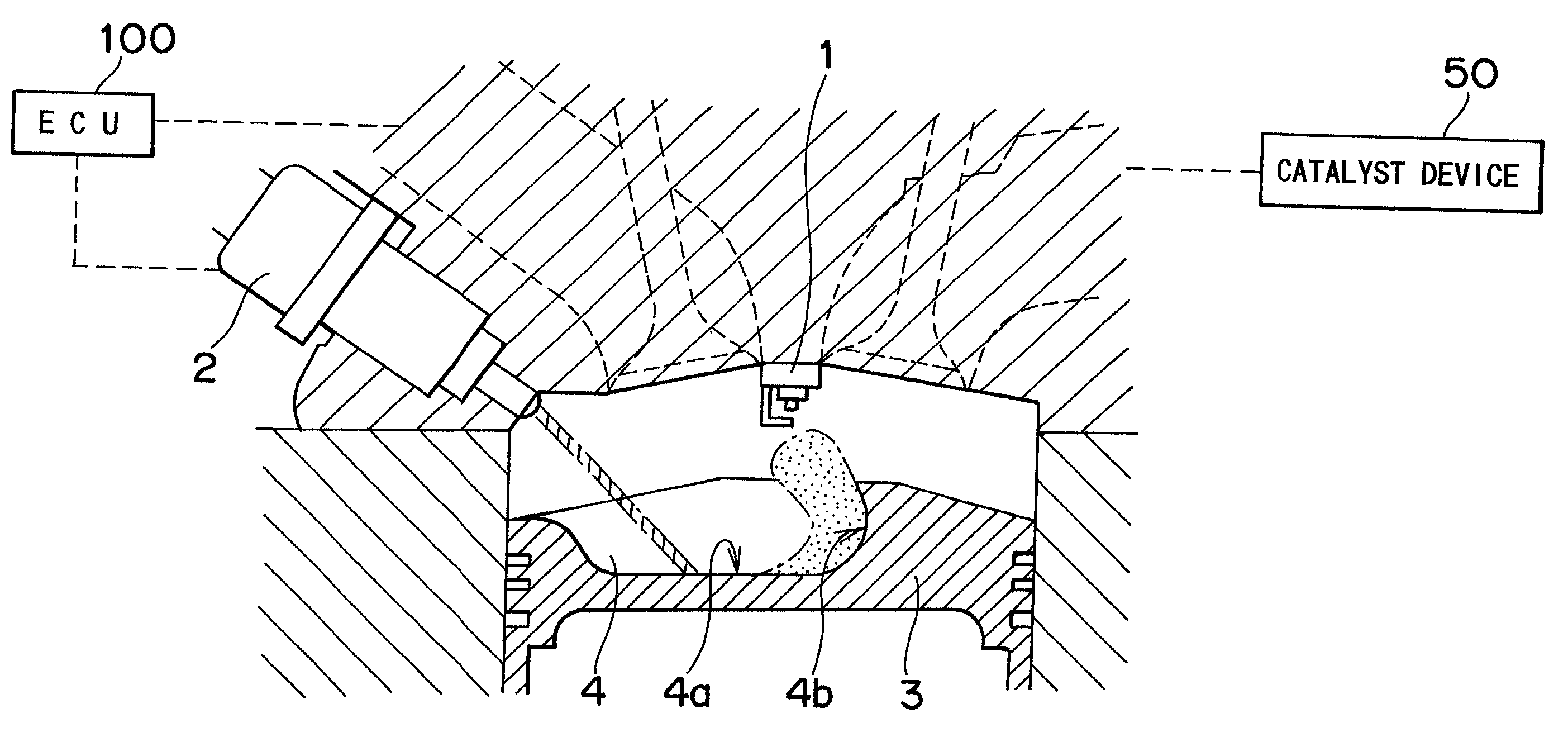
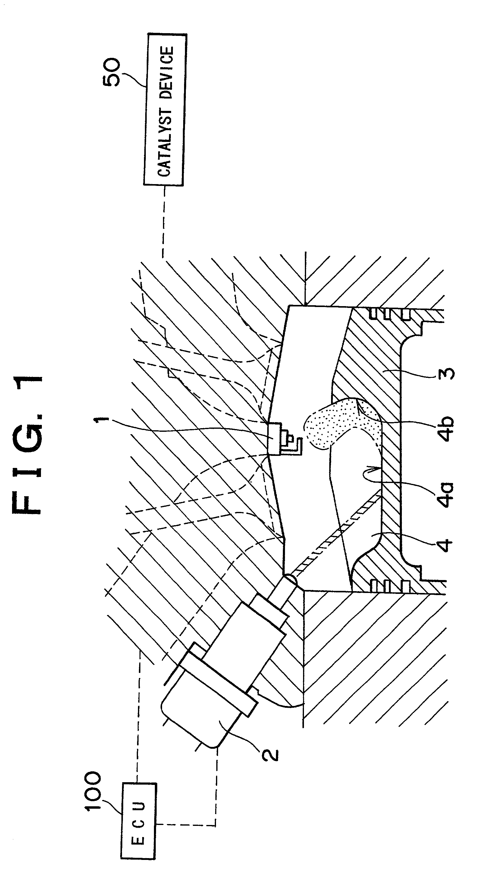
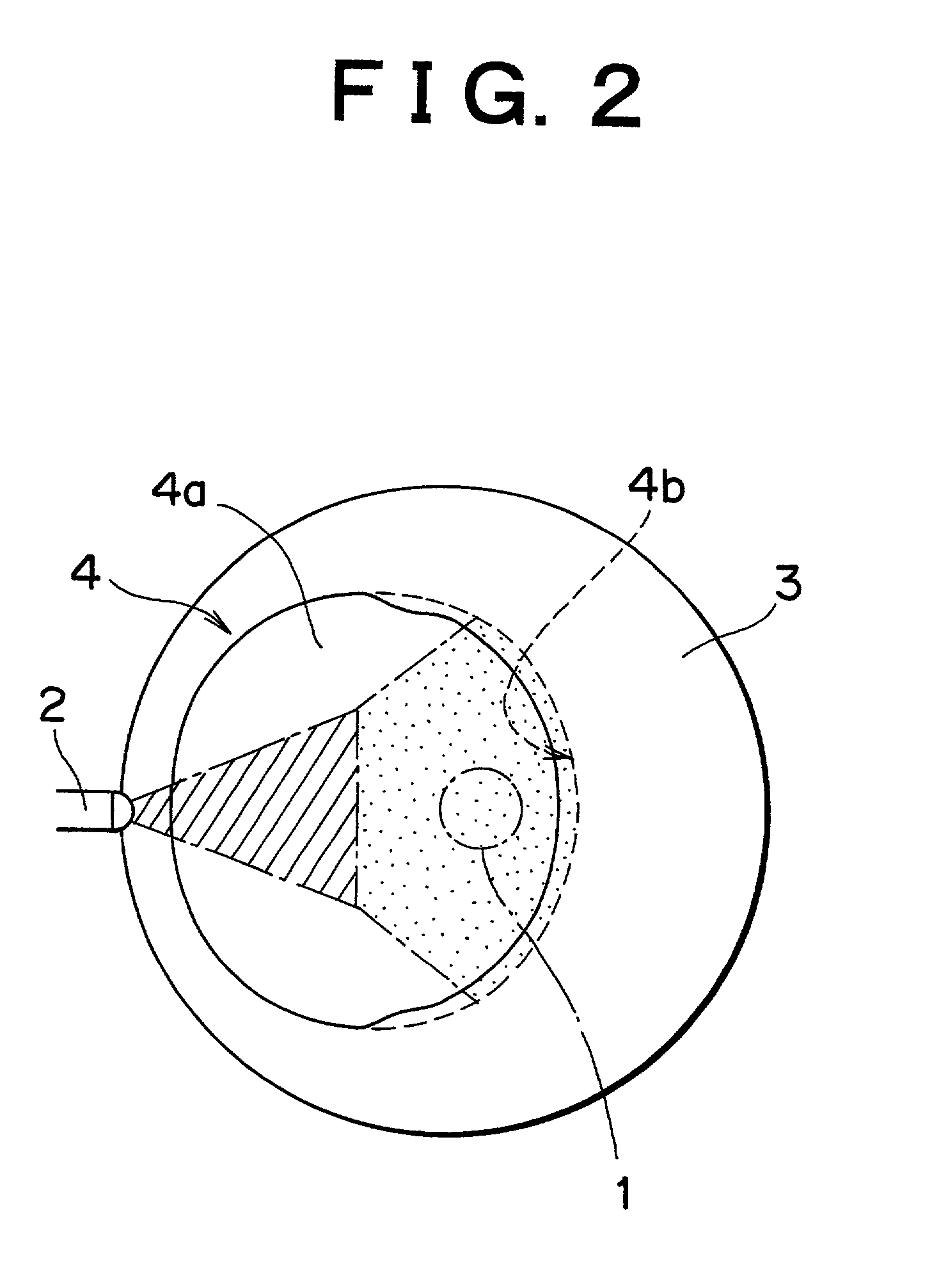
[0017] FIG. 1 is a schematic view in a longitudinal section of one of a plurality of cylinders for an in-cylinder injection type spark-ignition internal combustion engine constructed according to one preferred embodiment of the invention. FIG. 2 is a top plan view of a piston used in the engine cylinder of FIG. 1. As is apparent from FIGS. 1 and 2, a spark plug 1 is disposed in a substantially central portion of the upper end of the cylinder. A fuel injection valve 2 is disposed in a peripheral portion of the upper end of the cylinder so as to allow direct injection of the fuel into the cylinder. A cavity 4 in the form of a recess is formed in a top face of a piston 3. The fuel injection valve 2 is located on the side of an inlet port at which the temperature is kept relatively low owing to the intake air flowing through the intake port so as to prevent vaporization of the fuel.

[0018] The fuel injection valve 2 preferably has a slit-like injection hole such that the fuel injected fr...


PUM


Abstract

In an in-cylinder injection spark-ignition internal combustion engine including a plurality of cylinders and a catalyst device disposed in an exhaust system of the engine, a fuel is injected to at least one selected cylinder selected from the plurality of cylinders to be operated, and subsequently the fuel is injected to all cylinders to be operated. At this time, a warm-up controlled variable for the at least one selected cylinder is smaller than the warm-up controlled variable used when all cylinders are operated. In the in-cylinder injection spark-ignition internal combustion engine, the all cylinder operation is started and the warm-up control is started for all cylinders to warm up the catalyst device disposed in the exhaust system of the engine preferably when a fuel injection pressure exceeds a target value.

Description

BACKGROUND OF THE INVENTION[0001] 1. Field of Invention[0002] The invention relates to an in-cylinder injection type spark-ignition internal combustion engine and method of operating same.[0003] 2. Description of Related Art[0004] There is a known in-cylinder injection type spark-ignition internal combustion engine, in which a fuel is injected directly into each cylinder of the engine during a latter half of a compression stroke. This may provide a fine combustible air-fuel mixture concentrated around a spark plug, which allows a stratified charge combustion that assures combustion of the air-fuel mixture within the cylinder while keeping an overall air-fuel ratio of the air-fuel mixture lean. In such an in-cylinder injection type spark-ignition internal combustion engine, each of the cylinders is provided with a fuel injection valve for injecting a highly pressurized fuel stored in an accumulator into the cylinder. This arrangement makes it possible to inject the fuel into the cyli...

Claims


Application Information

Patent Timeline
Patent Type & Authority Applications(United States)
IPC IPC(8): F02D45/00F01N3/20F01N3/24F02B13/00F02B75/12F02D17/02F02D37/02F02D41/02F02D41/06F02D41/34F02D41/40
CPCF02B2075/125F02D37/02F02D41/008F02D41/0255F02D41/064F02D2041/389Y02T10/123Y02T10/26Y02T10/12F02B13/00
Inventor MIYASHITA, SHIGEKI
Owner TOYOTA JIDOSHA KK
Why Eureka
Try Eureka