Optical power managed network node for processing dense wavelength division multiplexed optical signals

a technology of optical signals and network nodes, applied in multiplex communication, transmission monitoring, instruments, etc., can solve the problems of optical signals that are "added" to the network at the optical add/drop network node that are subject to multiplexing function loss, and the power of the optical signal is typically affected by multiplexing function loss, so as to achieve efficient and cost-effective

Inactive Publication Date: 2002-02-21
DIGITAL LIGHTWAVE +1
View PDF0 Cites 14 Cited by
  • Summary
  • Abstract
  • Description
  • Claims
  • Application Information

AI Technical Summary

Benefits of technology

0012] The primary object of the present invention is to provide an optical power managed network node for processing dense wavelength division multiplexed optical signals in an efficient and cost effective manner.

Problems solved by technology

Also, most existing optical add / drop network nodes typically inflict some degree of loss upon the power of the optical signals that are received at each network node.
All of the above-described demultiplexing, switching, and multiplexing functions typically inflict some degree of loss upon the power of the optical signals that are received at the optical add / drop network node.
Thus, optical signals that are "added" to the network at the optical add / drop network node are also typically subject to multiplexing function losses.
Additionally, differences in power between "added" optical signals and optical signals that are otherwise received at most existing optical add / drop network nodes can cause problems such as, for example, channel crosstalk, in the resulting dense wavelength division multiplexed optical signal that is transmitted further along the network from the optical add / drop network node.
That is, when "added" optical signals are combined (i.e., multiplexed) with optical signals that are otherwise received at the optical add / drop network node, the higher power optical signals often interfere with the lower power optical signals.
Obviously, the above-described manual network initialization procedure can be costly in terms of both time spent by a network operator and the cost of optical power measurement and adjustment equipment.

Method used


Image

  • Optical power managed network node for processing dense wavelength division multiplexed optical signals
  • Optical power managed network node for processing dense wavelength division multiplexed optical signals
  • Optical power managed network node for processing dense wavelength division multiplexed optical signals

Examples


Embodiment Construction

)

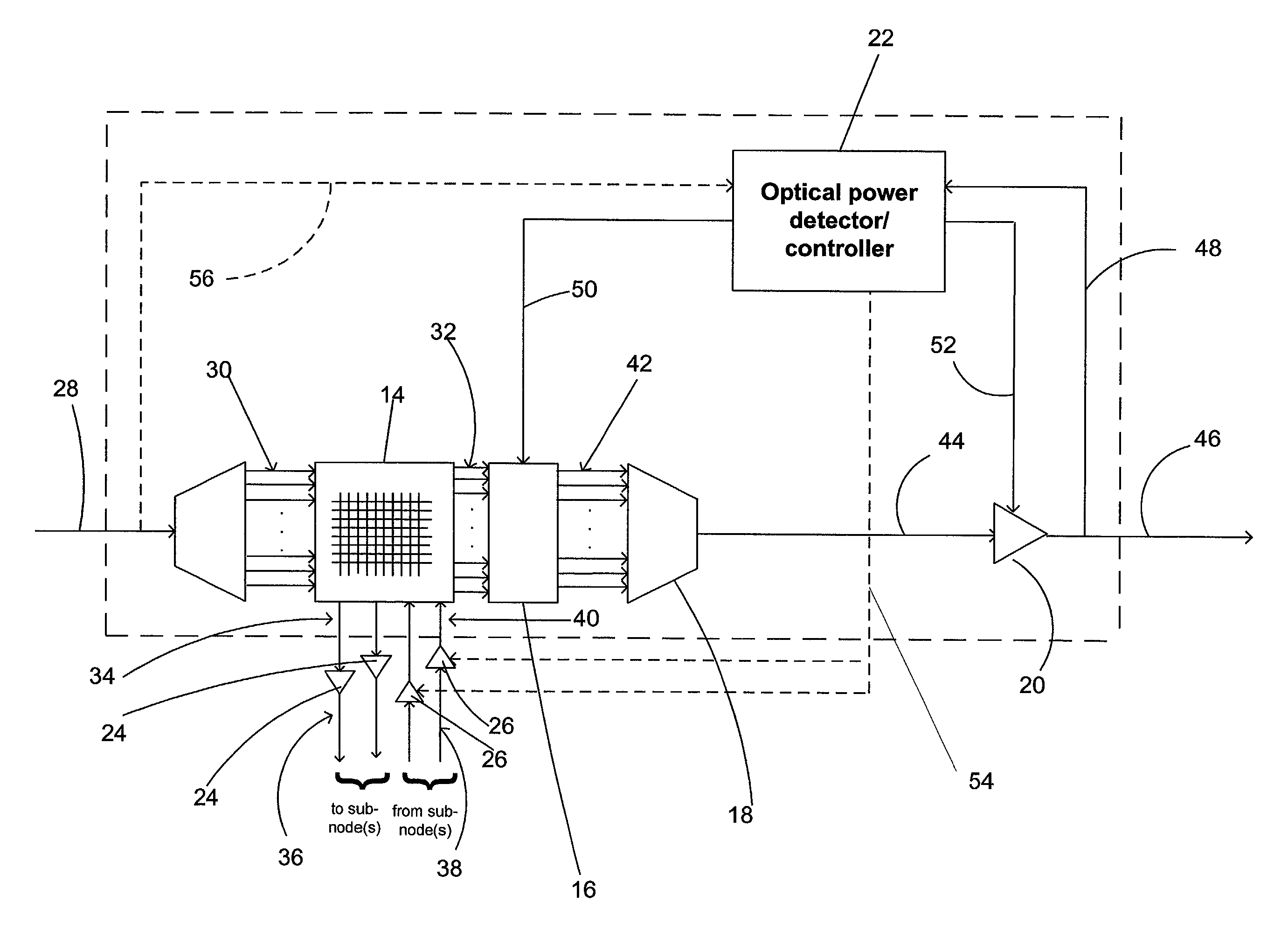
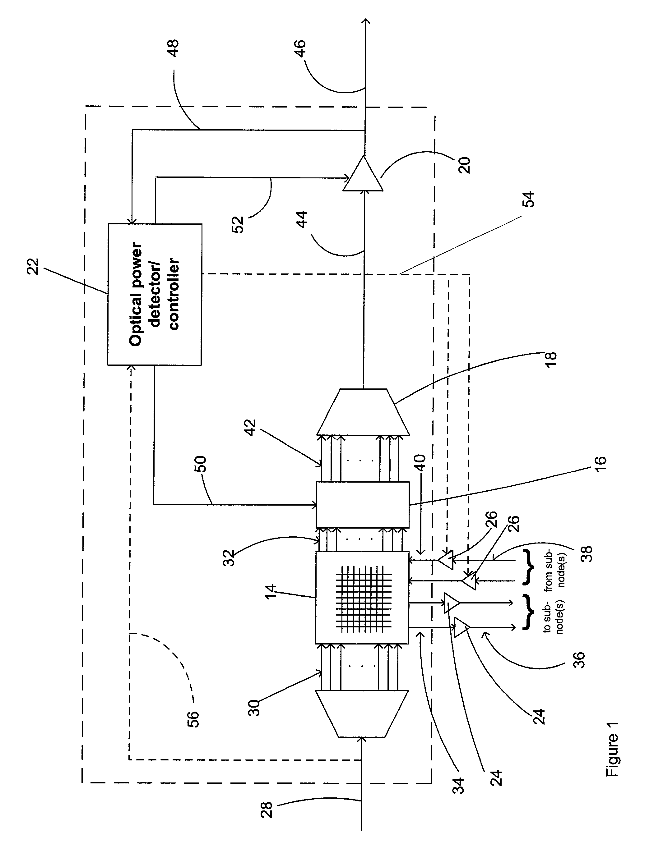
[0030] Referring to FIG. 1, there is shown a schematic diagram of a preferred embodiment of an optical power managed network node for processing dense wavelength division multiplexed optical signals in accordance with the present invention. The optical power managed network node 10 comprises a demultiplexing device 12, a switching device 14, a plurality of variable optical attenuators 16, a multiplexing device 18, a variable optical amplifier or gain element 20, a wavelength-selective optical power detector / controller 22, a first plurality of optical receivers / transmitters 24, and a second plurality of optical transmitters / receivers 26. The optical power managed network node 10 operates, through its aforementioned constituent parts, as follows.

[0031] The demultiplexing device 12 receives a first dense wavelength division multiplexed (DWDM) polychromatic optical signal on an optical input fiber 28. The first DWDM polychromatic optical signal contains a first plurality of narrowband ...


PUM


Abstract

A technique for processing dense wavelength division multiplexed optical signals in a network node is disclosed. In one embodiment, the technique is realized as an optical power managed network node comprising a dense wavelength division multiplexing device for combining a plurality of narrowband optical signals into a multiplexed polychromatic optical signal. The optical power managed network node also comprises a wavelength-selective optical power detector for detecting the power of each of the plurality of narrowband optical signals combined into the multiplexed polychromatic optical signal. The optical power managed network node further comprises a plurality of attenuators for attenuating the power of at least one of the plurality of narrowband optical signals based upon the detected power of each of the plurality of narrowband optical signals.

Description

[0001] This patent application claims priority to U.S. Provisional Patent Application No. 60 / 187,101, filed Mar. 6, 2000, which is hereby incorporated by reference herein in its entirety.[0002] This patent application is related to U.S. patent application Ser. No. 09 / 578,721, filed May 26, 2000, which is hereby incorporated by reference herein in its entirety.[0003] The present invention relates generally to dense wavelength division multiplexing networks and, more particularly, to an optical power managed network node for processing dense wavelength division multiplexed optical signals.[0004] Dense wavelength division multiplexing (DWDM) networks typically comprise a plurality of network nodes for receiving and transmitting dense wavelength division multiplexed optical signals. Each of the plurality of network nodes typically allows an individual optical signal that is contained in a received dense wavelength division multiplexed optical signal to either simply pass through the net...

Claims


Application Information

Patent Timeline
Patent Type & Authority Applications(United States)
IPC IPC(8): H04B10/08H04J14/02H04Q11/00
CPCH04B10/077H04B10/07955H04J14/0221H04Q11/0005H04Q2011/005H04Q2011/0058
Inventor TURNER, IANEMKEY, WILLIAM L.WADE, ROBERT K.
Owner DIGITAL LIGHTWAVE
Why Eureka
Try Eureka