Tool path preparing method and machining method

a tool path and machining technology, applied in the direction of total factory control, programme control, electric programme control, etc., can solve the problems of scars (cutter marks) generated on the workpiece, the cutting of which includes the shape perpendicular to or approximately and the inability to cut the part perpendicular to the main spindl

Inactive Publication Date: 2002-02-28
STAR MICRONICS
View PDF4 Cites 4 Cited by
  • Summary
  • Abstract
  • Description
  • Claims
  • Application Information

AI Technical Summary

Problems solved by technology

However, there are the following problems in the tool path preparing method and machining method as disclosed in JP-A-63-200943.
If the path of the roughing tool is prepared by shifting the finishing tool in the direction of the main spindle by an offset distance between the roughing tool and the finishing tool, and further shifting it in the direction perpendicular to the main spindle by the finishing allowance, a cutting which includes the shape perpendicular to or approximately perpendicular to the main spindle (

Method used


Image

  • Tool path preparing method and machining method
  • Tool path preparing method and machining method
  • Tool path preparing method and machining method

Examples


Embodiment Construction

[0035] Preferred embodiments of a tool path preparing method and a machining method will be described in detail below according to the present invention, with reference to the accompanying drawings. In this connection with the description on the drawings, the same parts as those of the conventional one are denoted by assigning the same reference numerals, and the duplication of the explanation will be omitted. In the present embodiments, an example in which the present invention is applied to a machine tool, and particularly, to a Swiss type machine tool, will be shown.

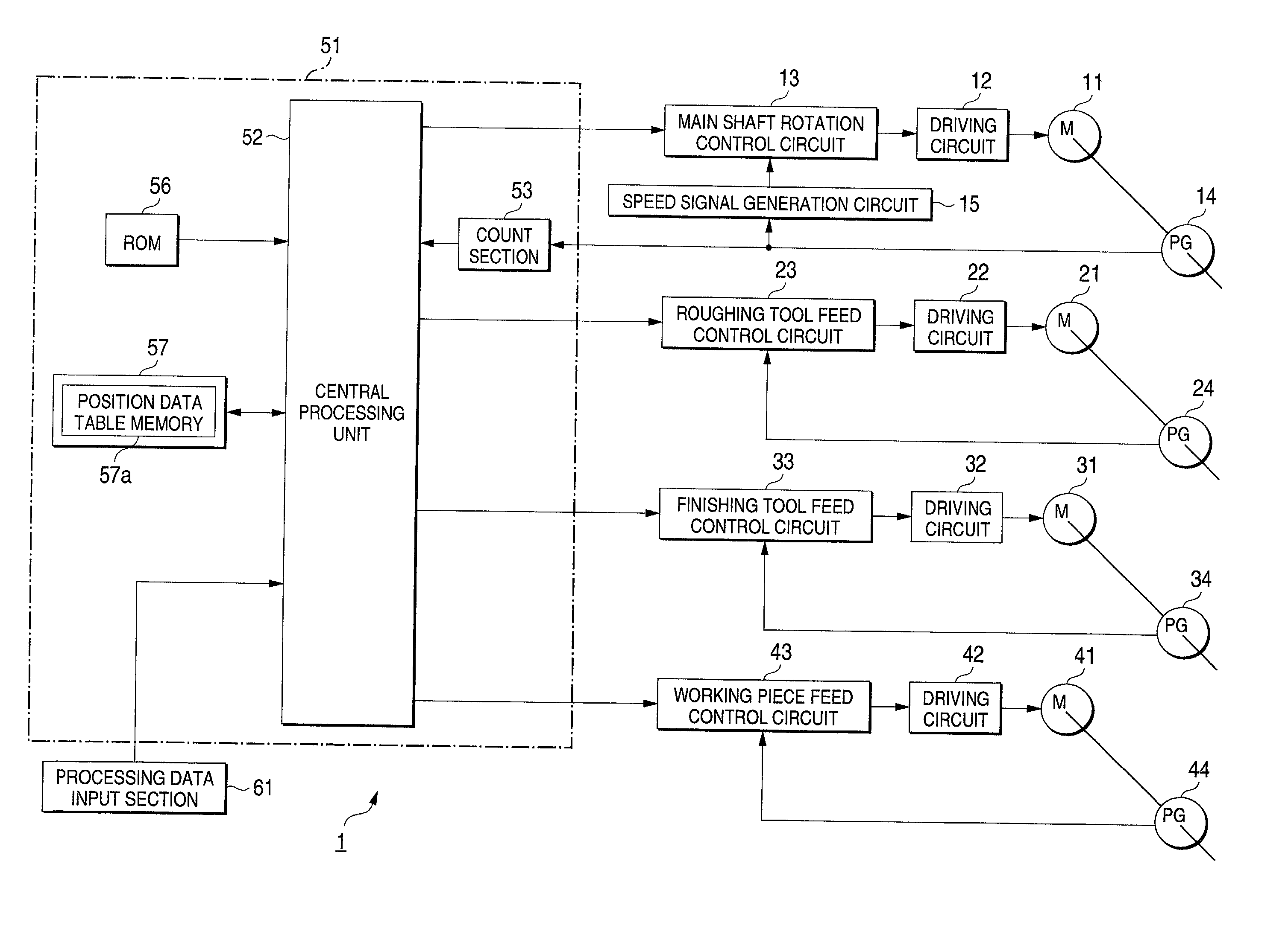
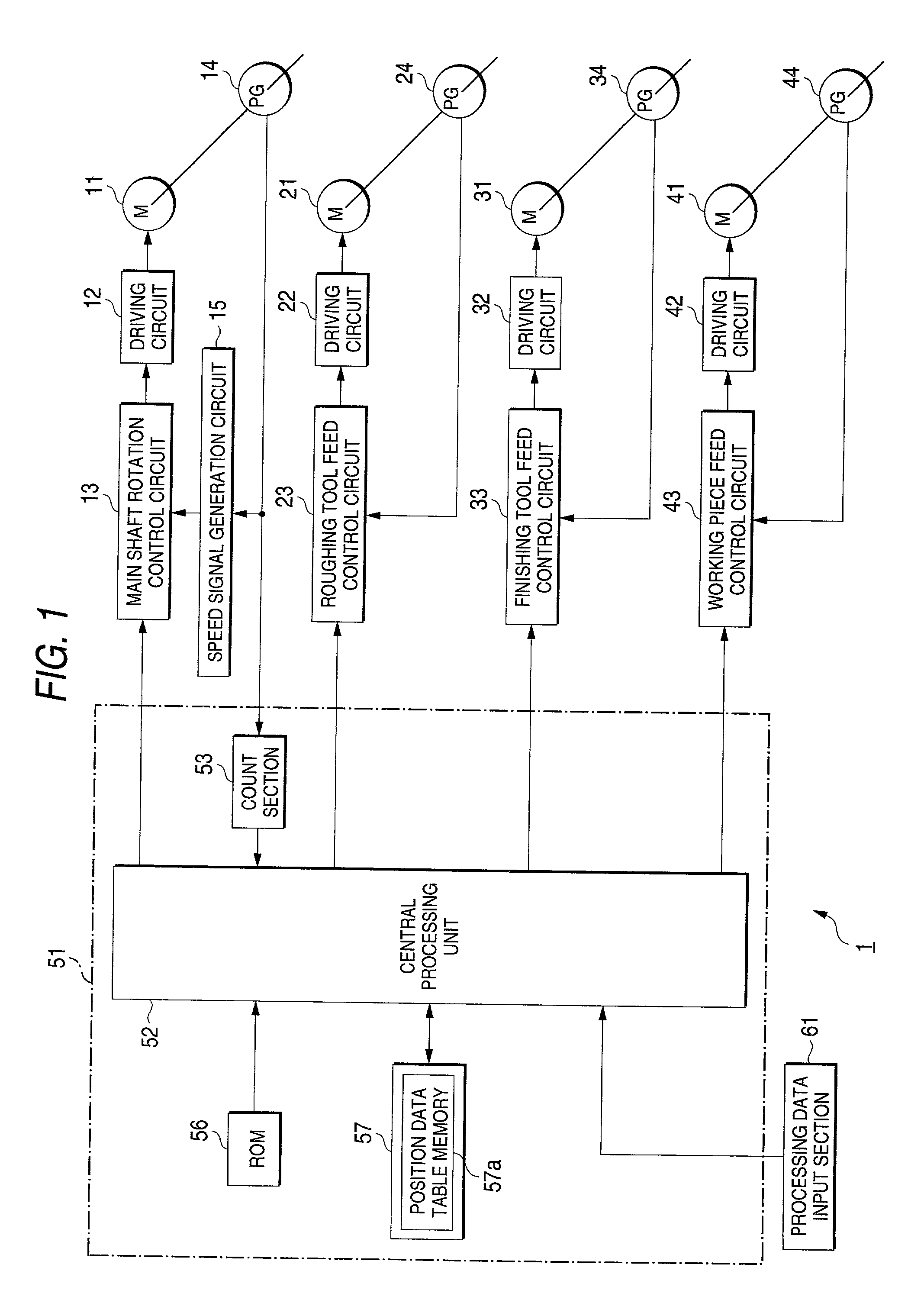
[0036] FIG. 1 is a block diagram showing the structure of a machine tool according to an embodiment of the present invention. In FIG. 1, a machine tool 1 has a main spindle rotation motor 11, roughing tool movement motor 21, finishing tool movement motor 31, workpiece movement motor 41, and control unit section 51 for controlling the drive of each of the motors 11, 21, 31, and 41.

[0037] The main spindle rotation motor...


PUM

PropertyMeasurementUnit
Speedaaaaaaaaaa

Abstract

The movement position of the roughing tool is calculated, in S109, by adding the finishing allowance to the movement position of the finishing tool so that the path of the roughing tool is shifted in the direction perpendicular to the rotation center axis of the main spindle rotation motor from the path of the finishing tool by the finishing allowance. Then, a gap between the movement position of the roughing tool in the direction of the rotation center axis of the main spindle rotation motor and the workpiece W is calculated, and when the gap is not larger than a predetermined value G, in S113, the movement position of the roughing tool is corrected in the direction perpendicular to the rotation center axis of the main spindle rotation motor so that the roughing tool does not cut in the inside of the finishing portion of the workpiece. The movement position of the roughing tool is corrected so that the movement speed of the roughing tool in the direction perpendicular to the rotation center axis of the main spindle rotation motor is a predetermined value.

Description

[0001] 1. Field of the Invention[0002] The present invention relates to a tool path preparing method for preparing a tool path to simultaneously conduct a roughing and finishing operations, and to a machining method employing the tool path preparing method.[0003] 2. Description of the Related Art JP-A-63-200943 discloses a tool path preparing method and a machining method employing the tool path preparing method, for example. According to JP-A-63-200943, controlling a position of a finishing tool automatically controls another tool to operate simultaneously at a rough-cut position having a smaller depth of cut by an arbitrarily given finishing allowance. In other words, only the position of the tip of the finishing tool is programmed, and the roughing tool is automatically controlled at a rough cut position leaving only the finishing allowance.[0004] However, there are the following problems in the tool path preparing method and machining method as disclosed in JP-A-63-200943.[0005]...

Claims


Application Information

Patent Timeline
IPC IPC(8): B23Q15/00G05B19/18G05B19/4093
CPCG05B19/182G05B2219/35525G05B2219/50008G05B2219/50015G05B2219/50087G05B2219/50088G05B2219/50336Y02P90/02
Inventor SEI, YOSHIHIROKAJIYAMA, TAKEHISAENDO, NOBUYUKISHIBAZAKI, KUNIHISA
Owner STAR MICRONICS
Why Eureka
Try Eureka