Correlation detecting method and matched filter unit

a filter unit and correlation detection technology, applied in the field of correlation detection methods and matched filter units, can solve the problems of difficult to meet the miniaturization, power saving prerequisites, and low manufacturing costs

Inactive Publication Date: 2002-03-07
PANASONIC CORP
View PDF0 Cites 5 Cited by
  • Summary
  • Abstract
  • Description
  • Claims
  • Application Information

AI Technical Summary

Problems solved by technology

This is why the related art matched filter units described above have suffered from a problem that it is difficult to satisfy the miniaturizing, lower manufacturing cost, and power saving prerequisites.

Method used


Image

  • Correlation detecting method and matched filter unit
  • Correlation detecting method and matched filter unit
  • Correlation detecting method and matched filter unit

Examples


first embodiment

[0060] [First Embodiment]

[0061] At first, the first embodiment of the present invention will be described with reference to the accompanying drawings.

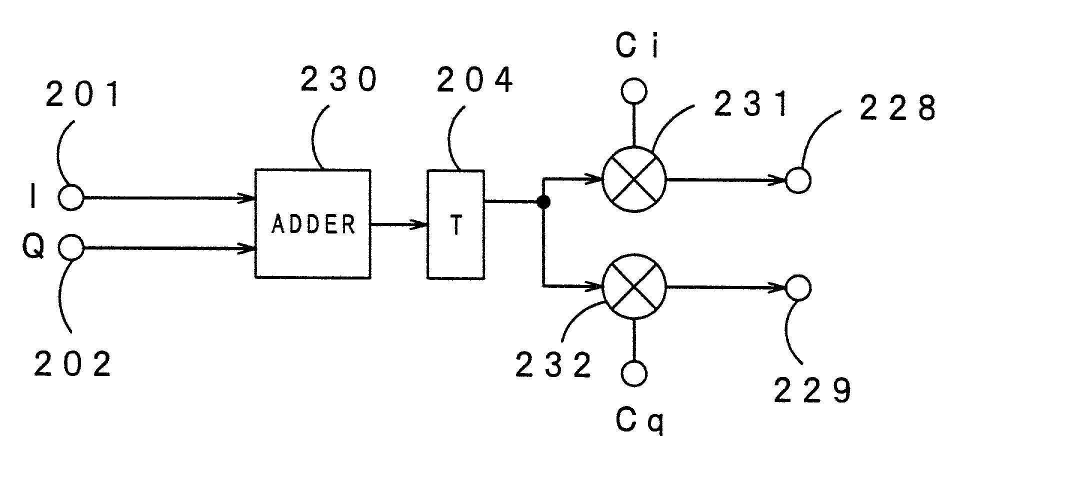
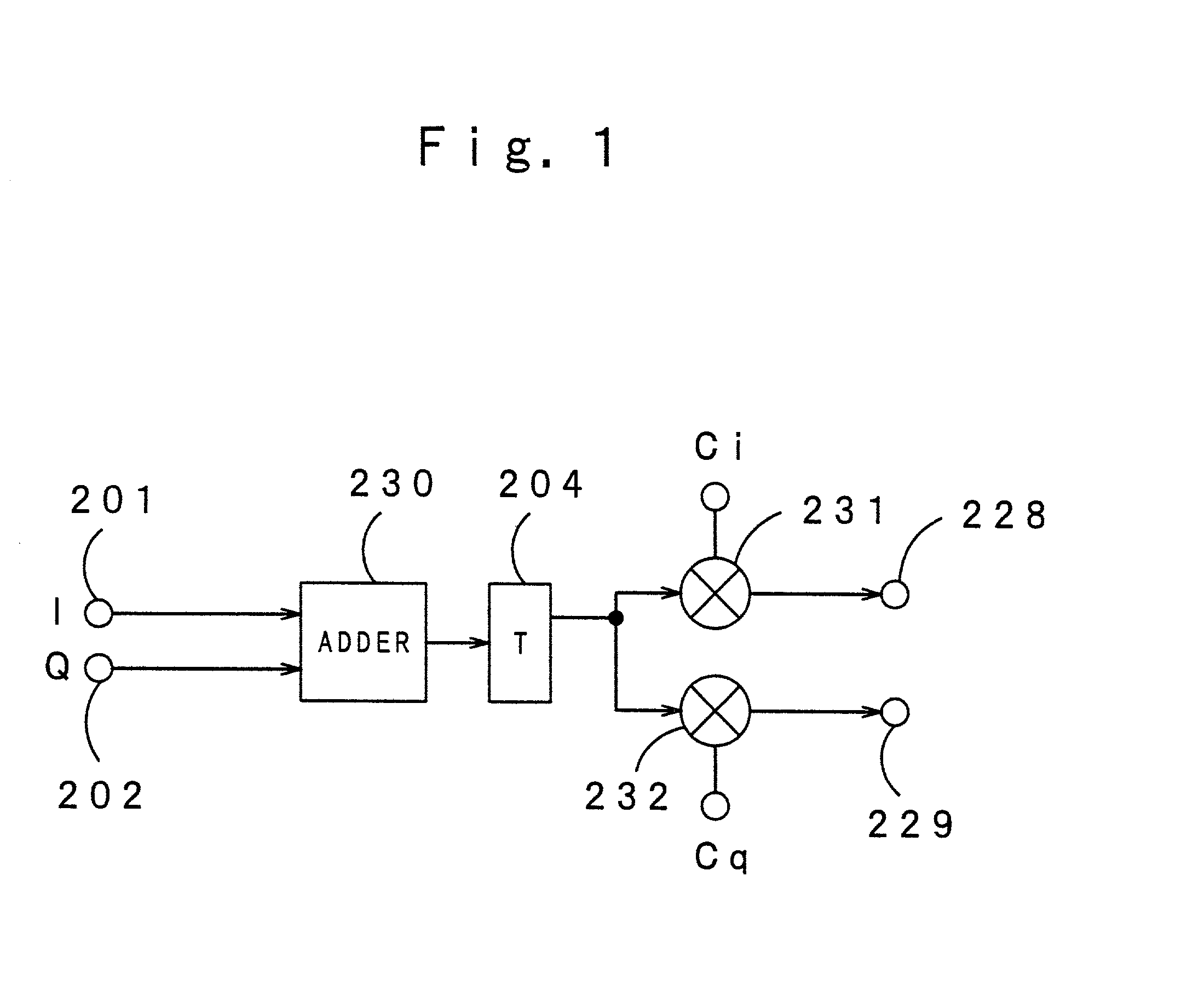
[0062] FIG. 1 indicates a conception of the correlation detecting method in the first embodiment of the present invention. In FIG. 1, 201 and 202 are input terminals, 204 is a storage circuit, 230 is a signal multiplexing circuit composed of an adder, 231 and 232 are back-diffusion computing devices, 228 and 229 are output terminals, Ci is a code value for performing back-diffusion of the digital signal I, and Cq is a code value for performing back-diffusion of the digital signal Q.

[0063] The correlation detecting method in this embodiment is characterized by that the digital signals I and Q are diffusion-modulated with different code values, then the modulated signals are multiplexed and stored. After this, each stored multiplexed signal is computed for back-diffusion according to the code value Ci or Cq.

[0064] As shown in FIG. 1, at ...

second embodiment

[0067] [Second Embodiment]

[0068] Hereunder, the second embodiment of the present invention will be described with reference to the accompanying drawings.

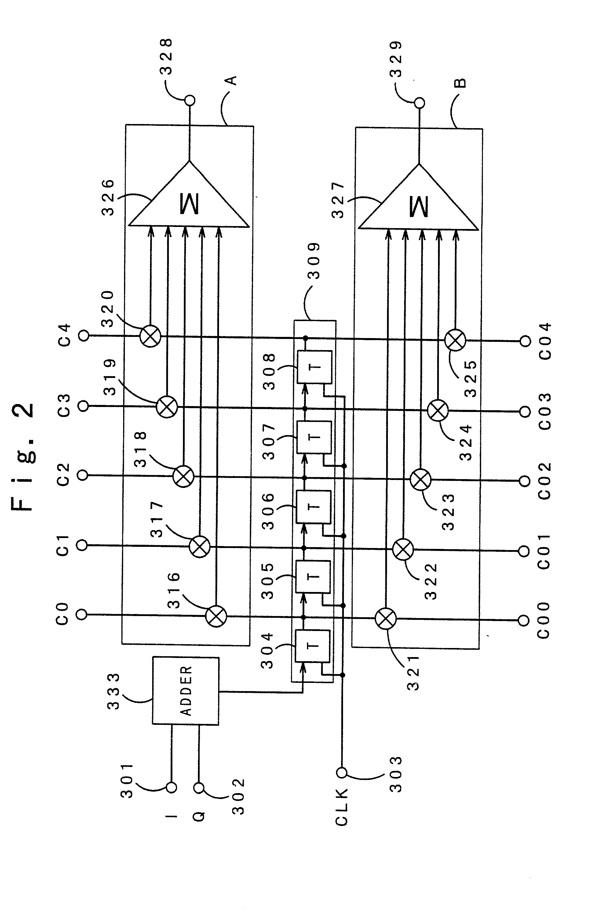
[0069] FIG. 2 is a configuration of the matched filter unit in the second embodiment of the present invention.

[0070] The matched filter unit in this second embodiment is a five-time diffusion five-tap one used to perform the correlation detecting method in the first embodiment. The matched filter unit, as shown in FIG. 2, comprises input terminals 301 and 302, a clock signal input terminal 303, a shift register (storage circuit) composed of delay circuits 304 to 308 disposed in 5 stages, multipliers 316 to 325, adders 326 and 327, output terminals 328 and 329, and a signal multiplexing circuit 333 composed of an adder. Each of the multipliers 316 to 320 of this matched filter unit uses corresponding one of the code values of the back-diffusion code string (digital code string) C4C3C2C1C0 for the digital signal I. The multipliers 316...

third embodiment

[0083] [Third Embodiment]

[0084] Hereunder, the third embodiment of the present invention will be described with reference to the accompanying drawings.

[0085] FIG. 4 indicates a concept of the correlation detecting method in the third embodiment of the present invention. In FIG. 4, 401 and 402 are input terminals. 404 is a storage circuit and 430 is a signal multiplexing circuit composed of an adder. 431 is a back-diffusion computing device and 432 is a code value switching circuit composed of a selector circuit. 428 is an output terminal and Ci is a code value for performing back-diffusion of the digital signal I and Cq is a code value for performing back-diffusion of the digital signal Q.

[0086] The correlation detecting method in this third embodiment is characterized as follows: The digital signals I and Q that are diffusion-modulated with different code values, then the signals are multiplexed and stored. After this, the stored multiplexed signal is computed for back-diffusion in...


PUM


Abstract

The matched filter unit of the present invention is used for finding a value of correlation between each of a plurality of digital signals synchronized with a clock and each of a plurality of digital code strings consisting of M (M: plural) digital codes respectively. The matched filter unit comprises a circuit for multiplexing a plurality of the digital signals, a storage circuit composed of delay circuits disposed in M stages and used for entering a signal output from the signal multiplexing circuit to the first stage delay circuit, then shifting the signal to the subsequent delay circuits sequentially in synchronization with the clock, and a plurality of computing devices for finding a value of correlation between each of the digital signals and a digital code string respectively using a signal output from each of the delay circuits disposed in M stages. Each of a plurality of the computing devices is composed of M multipliers (M: plural) for multiplying a signal output from each of the delay circuits by each digital code of a digital code string and an adder for adding results of multiplication from the M multipliers to find a value of the correlation. According to this configuration of the matched filter unit, a plurality of the digital signals that are diffusion-modulated with different code values are not correlative with each other. Those non-correlative digital signals are multiplexed by a signal multiplexing circuit, then the multiplexed signal is computed for back-diffusion in the storage circuit, the multipliers, and the adder using different digital code strings, thereby to detect a value of correlation between digital signals entered from a plurality of channels using the same storage circuit. It is thus possible to provide a matched filter unit that can be reduced significantly in circuitry size, thereby to satisfy the miniaturizing, lower manufacturing cost, and power saving prerequisites.

Description

[0001] 1. Field of the Invention[0002] The present invention relates to a method for detecting a correlation between digital signals using a spectrum communication system for pocket telephones and a matched filter unit that uses the correlation detecting method.[0003] 2. Description of the Related Art[0004] At first, a configuration of a related art matched filter unit will be described with reference to FIG. 6. FIG. 16 shows a configuration of the first related art matched filter unit used for receiving signals from two 5-time diffusion 5-tap channels, each composed of an FIR digital filter.[0005] This related art matched filter unit is provided with input terminals 1 and 2, a clock signal input terminal 3, a shift register 9 composed of five delay circuits 4 to 8 disposed in five stages, a shift register 15 composed of five delay circuits 10 to 14 disposed in five stages, multipliers 16 to 25, adders 26 and 27, and output terminals 28 and 29. Each of the multipliers 16 to 20 uses ...

Claims


Application Information

Patent Timeline
Patent Type & Authority Applications(United States)
IPC IPC(8): H03H17/02H04B1/7093H04J13/00H04L7/00
CPCH03H17/0254H04B1/7093
Inventor KURIHARA, NAOYUKI
Owner PANASONIC CORP
Why Eureka
Try Eureka