
"flame resistant pipe flange gasket"

Inactive Publication Date: 2002-03-14
PARKER HANNIFIN CORP
View PDF0 Cites 66 Cited by
  • Summary
  • Abstract
  • Description
  • Claims
  • Application Information

AI Technical Summary

Benefits of technology

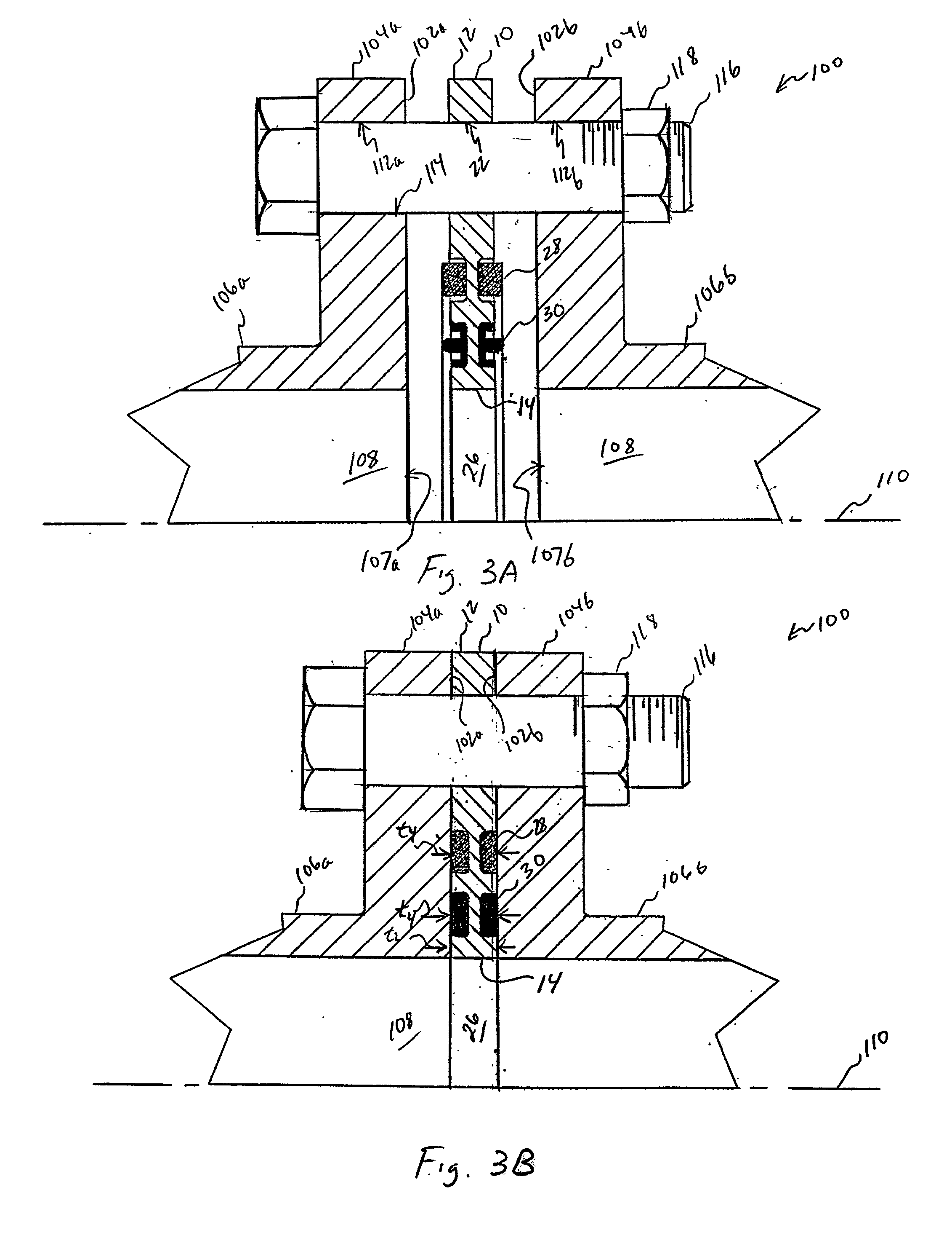
[0038] Further in such preferred embodiment, the outer seal members are formed of a layer of a lamellar, expanded graphite sheet material, i.e., laminated foil, which is both flame resistant and compressible in a fluid-tight sealing arrangement to conform to asperities or other irregularities between the interface surfaces of the pipe flanges with a minimum of compression set. The compression of both the inner and outer seal members of the gasket advantageously is delimited to an optimum thickness by the thickness of the metal retainer member. The metal retainer additionally provides for direct metal-to-metal contact between the interface surfaces of the pipe flanges to accommodate the development of high tensile stresses, with a minimum of torque loss from thermal cycling, in the bolts or other fastening members used to couple the interface surfaces into a joint assembly.
[0077] Referring lastly to FIGS. 6 and 7, another representative embodiment of gasket 10 of the present invention is shown generally at 300 wherein the elastomeric inner seal member 30 or 30' is eliminated to provide a generally continuous second backup portion 31b of retainer member 12 extending radially intermediate the inner periphery 14 thereof and outer mounting grooves 34. As in the other gasket embodiments illustrated herein, the retention of the outer seal elements within grooves 34 advantageously confines the elements and thereby, during deformation under load, minimizes the extrusion thereof which otherwise could compromise the integrity of the fluid seal.

Problems solved by technology

Should the elastomeric inner seal members eventually fail in the flame environment, however, the outer seal members afford a redundant sealing capability allowing the gasket to maintain its fluid integrity for an extended period of exposure.

Method used


Image

  • "flame resistant pipe flange gasket"
  • "flame resistant pipe flange gasket"
  • "flame resistant pipe flange gasket"

Examples


Embodiment Construction

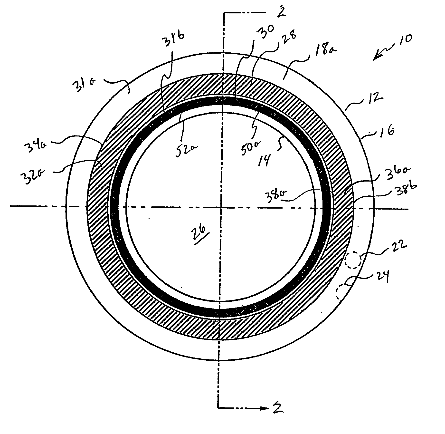
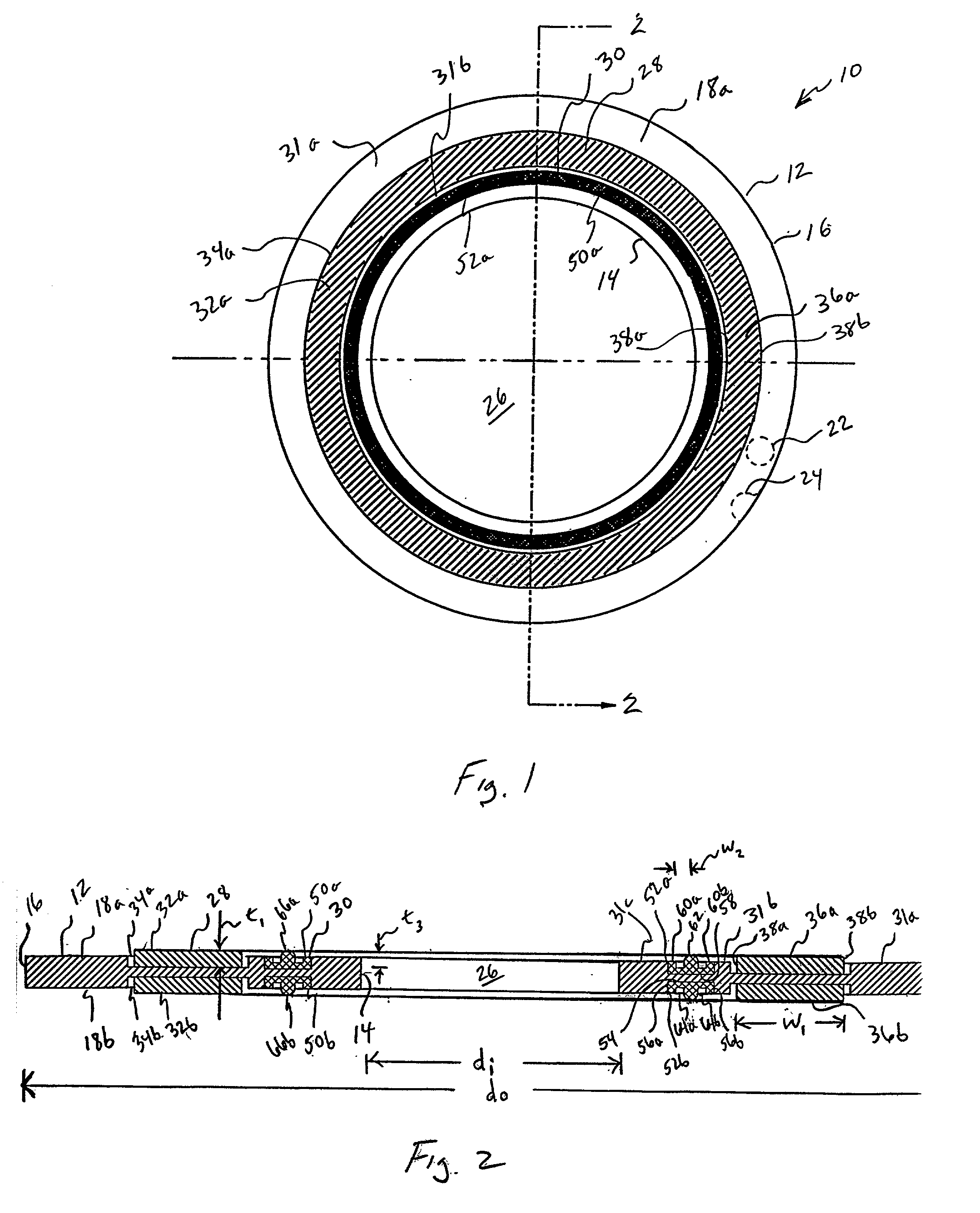
[0079] To confirm the precepts of the present invention a 1-inch pipe flange gasket, constructed in accordance with FIGS. 1 and 2 hereinabove as including expanded graphite foil outer seal elements and molded-in rubber inner seal elements, was subjected to leakage testing by Omega Point Laboratories, Inc., Elmendorf, Tex., in accordance with American Petroleum Institute (API) Standard 607 Fire Test For Soft-Seated Quarter-Turn Valves (modified). The test encompassed pressurizing the gasket with water from a source tank, and exposing the gasket to a hydrocarbon temperature curve as specified in the standard. During the test, leakage was measured by monitoring the water level in the source tank, and then calculating the volume change over time. The following leakage (Lkg) results were recorded:

1TABLE 1 (API) Standard 607 Fire Test Results Lkg @ Avg. Lkg. 212.degree. F. Lkg @ Avg. Lkg Rate Over Rate Over (ml) 40:00 min. (ml) Time to 212.degree. F. (ml / min) 40 min. (ml / min) 0 1.622 0 40...


PUM


Abstract

A flame resistant gasket for interposition between the interface surfaces of a pair of mating pipe flanges. The gasket includes a metal retainer member having generally planar first and second surfaces with at least one aperture formed therethrough which is configured for generally coaxial registration with a fluid passageway defined through the pipe flanges. At least one generally annular, flame resistant outer seal member is supported on the retainer member as disposed coaxially with the aperture thereof a spaced-apart, radially outward distance therefrom. The outer seal member has oppositely-disposed first and second outer radial sealing surfaces for abutting contact with a corresponding one of the interfaces surfaces, and is compressible axially between the interface surfaces for effecting a first fluid-tight seal about the fluid passageway. At least one generally annular, elastomeric inner seal member optionally is attached to the retainer member as disposed coaxially with the aperture thereof radially inwardly of the outer seal member. The inner seal member has oppositely-disposed first and second inner radial sealing surfaces for abutting contact with a corresponding one of the interfaces surfaces, and is compressible axially between the interface surfaces for effecting a second fluid-tight seal about the fluid passageway.

Description

RELATED CASES[0001] The present application claims priority to U.S. Provisional Application Ser. No. 60 / 067,595; filed Dec. 5, 1997.[0002] The present invention relates broadly to a sealing assembly or gasket adapted to provide a fluid seal intermediate a mating pair of pipe flanges, and more particularly to a composite, flame resistant pipe flange gasket construction incorporating one or more outer flame resistant seal members and, optionally, one or more inner elastomeric seal members, both such members being supported on a metal retainer member.[0003] Sealing gaskets of the type herein involved are employed in a variety of commercial and industrial fluid transport applications for compression between the opposing or faying surfaces of a pair of mating pipe flange ends to provide a fluid-tight interface sealing thereof. In basic construction, such gaskets are typically are formed of a relatively compressible, annular seal member having a central aperture configured for registratio...

Claims


Application Information

Patent Timeline
IPC IPC(8): F16J15/06F16J15/12F16L23/18
CPCF16J15/065F16J15/122F16J15/127F16L23/18
Inventor BETTENCOURT, ALAN C.
Owner PARKER HANNIFIN CORP
Learn More