
Cutting, tool system and mechanism for accurately positioning a cutting edge

a technology of cutting edge and tool system, which is applied in the direction of tool holders, mechanical devices, manufacturing tools, etc., can solve the problems of limited space inside the workpiece, chip jamming, and damage to tools

Inactive Publication Date: 2002-03-28
SANDVIK INTELLECTUAL PROPERTY AB
View PDF0 Cites 25 Cited by
  • Summary
  • Abstract
  • Description
  • Claims
  • Application Information

AI Technical Summary

Benefits of technology

[0009] The aims of the present invention are to eliminate the disadvantages of previously known methods for determining the exact position of the operative cutting edge.
[0010] The first objective is to create a system which can be used on a bar which is substantially cylindrical, i.e., the requirement of one or several planar reference surfaces or a deep "V" groove which weakens the bar is avoided.
[0011] A second objective is to provide a system which is simple and lends itself to easy use in the confined space, poor lighting and dirty environment found in a machine tool, and which can also be a useful aid for machine operators who are blind or have poor sight.
[0012] Thirdly to create a system that can be reasonably priced when supplied on new tools or as conversion kits for older installations.

Problems solved by technology

Firstly, there is a limited space inside the workpiece.
The limited space inside the workplace within which the tool must operate also makes chip forming, chip flow and chip breaking far more critical than in external turning operations since the failure of any of these chip-related activities can lead to chip jamming, damaged tools, poor finish on the machined surfaces and tool vibration.
Secondly, internal turning operations differ from external ones in that vibration of the tool is always present and it has a major influence on tool life, surface finish and productivity.
Incorrect positioning of the cutting edge may lead directly to cutting forces which differ from those for which the tool was designed, and the negative effects on chip forming will also often lead to vibration.
This solution has the disadvantage (already mentioned) that the machining of the planar surface decreases the material in the bar and hence its strength.
Furthermore the use of a spirit level is not desirable because of the limited space and poor accessibility in a modern machine tool plus the difficulties of reading a spirit level in the presence of cooling fluid and chips.
This solution is time consuming to use and is not suitable for the limited space and poor accessibility in a machine tool.

Method used


Image

  • Cutting, tool system and mechanism for accurately positioning a cutting edge
  • Cutting, tool system and mechanism for accurately positioning a cutting edge
  • Cutting, tool system and mechanism for accurately positioning a cutting edge

Examples


Embodiment Construction

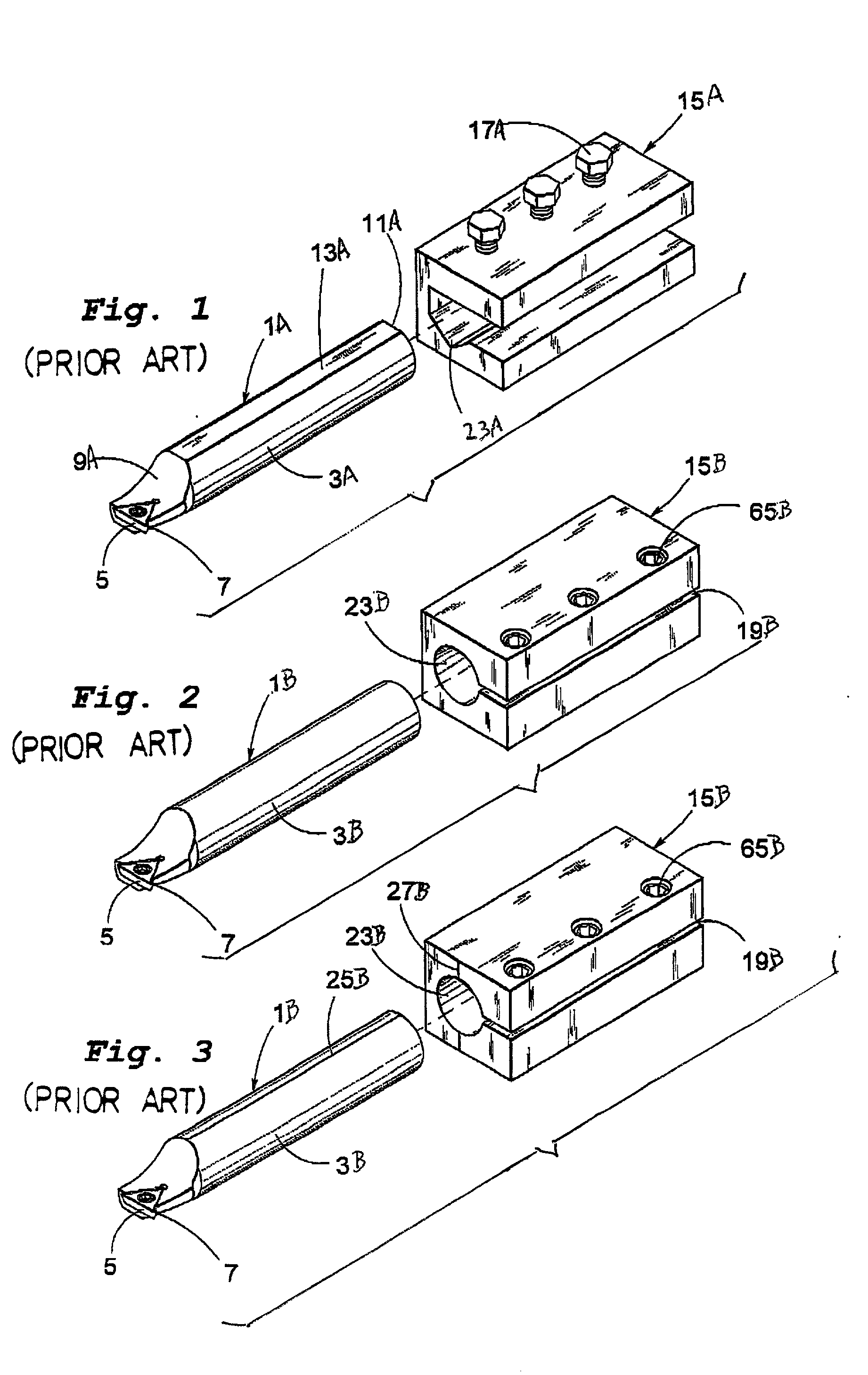
[0030] FIG. 1 illustrates a typical prior art combination consisting of a cutting tool 1A, for example a boring bar, and a tool-clamping device 15A. The cutting tool consists of a substantially cylindrical shaft portion 3A with front 9A and rear ends 11A. The front end accommodates at least one cutting insert 5. The cutting tool 1A is located and secured in the tool clamping device 15A by means of at least one clamping screw 17A acting on a planar surface 13A formed on the upper side of the bar. The lower part of an aperture 23A formed in the tool block is V-shaped. This solution is commonly used but is not recommended since it gives a limited clamping force because of the restricted contact surface of the tips of the screws on the surface 13A and poor location of the bar and hence poor repeatable accuracy of the height of the cutting edge 7.

[0031] FIG. 2 illustrates another prior art clamping method in which a substantially cylindrical cutting tool 1B is accommodated in a correspon...


PUM

PropertyMeasurementUnit
angleaaaaaaaaaa
angleaaaaaaaaaa
angleaaaaaaaaaa

Abstract

A cutting tool system includes a clamping device and a cutting tool mounted therein. The cutting tool carries a cutting edge and includes a shaft clamped within an aperture of the clamping device. Prior to being clamped, the shaft is movable relative to the clamping device in either a longitudinal or rotational direction, in order to locate the cutting edge in a desired position. Either the clamping device or the cutting tool carries a spring-loaded device which engages a recess formed in the other of the cutting tool and clamping device when the cutting tool and its cutting edge are in a desired position, to provide an indication that the cutting tool is in such desired position by providing a sudden increase in a force necessary to displace the cutting tool out of such desired position.

Description

[0001] This application is based on and claims priority of Swedish Patent Application No. 0001473-8, filed Apr. 20, 2000, the disclosure of which is incorporated by reference herein.[0002] This invention relates to a system for rapidly and accurately establishing the correct position of the operative cutting edge on tools for chip forming metal machining and in particular those used for internal turning such as boring bars which are clamped in tool clamping devices. Said cutting tools comprise a shaft and at least one cutting edge disposed at one end or both ends of the shaft. The cutting edge can be disposed on a cutting insert which can be attached to the cutting tool mechanically, for example by use of a screw, or metallurgically, for example by welding. Alternatively, the cutting edge can be an integral part of a solid, one piece tool shank. The cutting edge is positioned offset from the longitudinal axis of the cutting tool and at a greater distance from said axis than any othe...

Claims


Application Information

Patent Timeline
Patent Type & Authority Applications(United States)
IPC IPC(8): B23B29/00B23B29/04
CPCB23B29/04B23B2260/004B23B2260/088Y10T82/2591Y10T82/2543Y10T82/2589Y10T82/2585Y10T82/30Y10T279/13B23B29/06
Inventor ERICKSSON, HAKANSORLUND, TRYGGVE
Owner SANDVIK INTELLECTUAL PROPERTY AB
Features
  • Generate Ideas
  • Intellectual Property
  • Life Sciences
  • Materials
  • Tech Scout
  • Unparalleled Data Quality
  • Higher Quality Content
  • 60% Fewer Hallucinations
Learn More