
Ink bottle mounting apparatus and ink bottle for the apparatus

a technology for mounting apparatuses and ink bottles, applied in inking apparatuses, printing press parts, instruments, etc., can solve problems such as excessive increase of locking force and troublesome replacement operation

Inactive Publication Date: 2002-03-28
RISO KAGAKU CORP
View PDF8 Cites 9 Cited by
  • Summary
  • Abstract
  • Description
  • Claims
  • Application Information

AI Technical Summary

Benefits of technology

[0010] The present invention has been accomplished to solve the above problems, it is an object of the invention to provide an ink bottle mounting apparatus and an ink bottle used for the apparatus in which the ink bottle can be locked in its mounting position and the ink bottle can easily be replaced. It is another object of the invention to provide an ink bottle mounting apparatus and an ink bottle used for the apparatus in which the ink bottle can be locked in its mounting position, the ink bottle can easily be replaced, and the ink bottle can reliably be locked with a predetermined locking force even if the entire length of the ink bottle is varied due to swelling of the ink bottle or the like.

Problems solved by technology

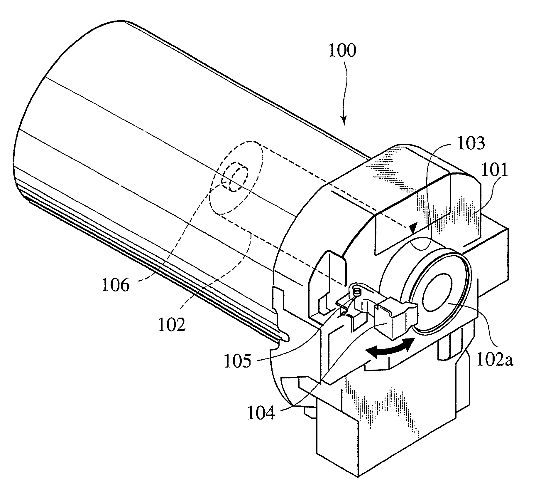
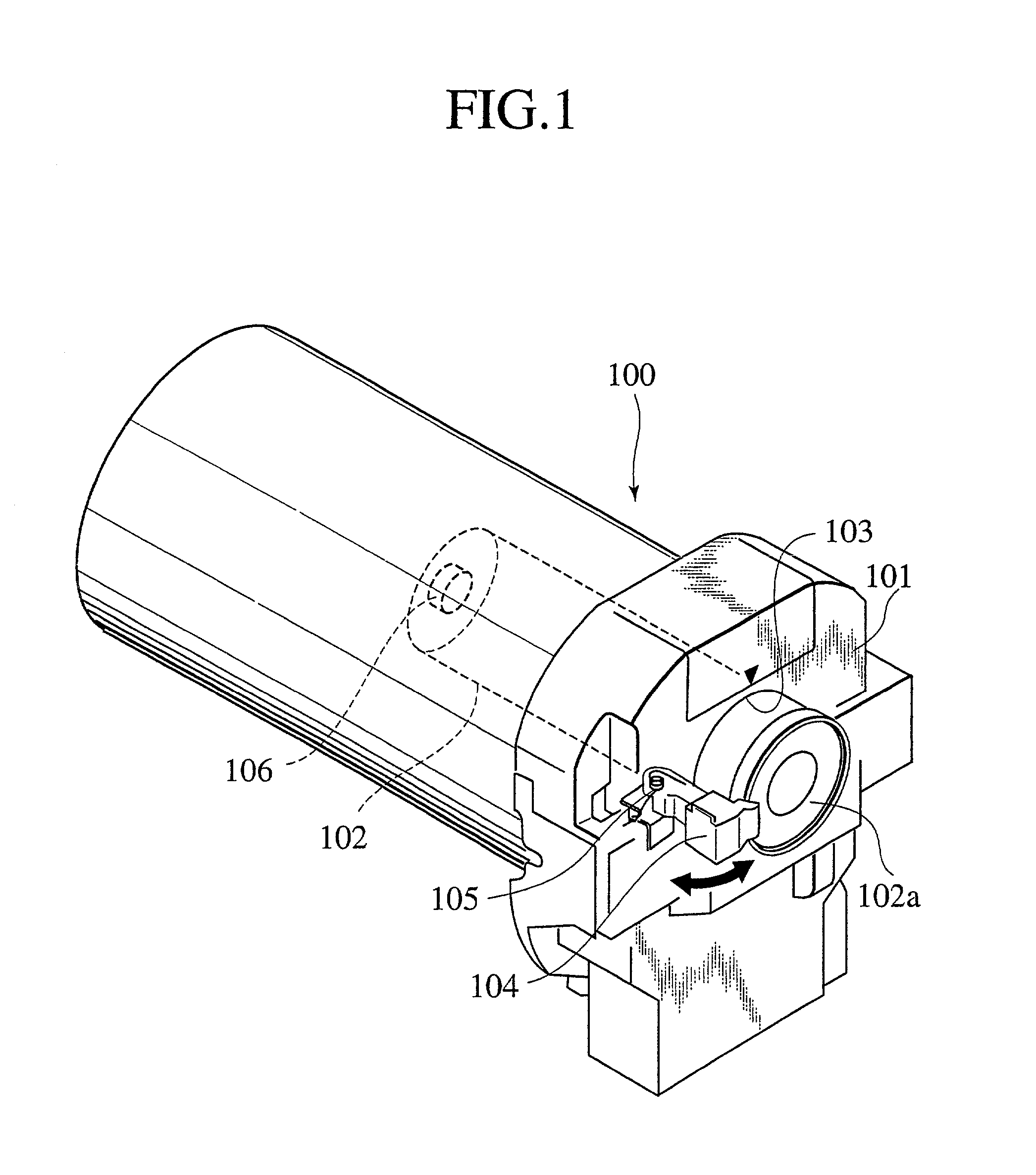
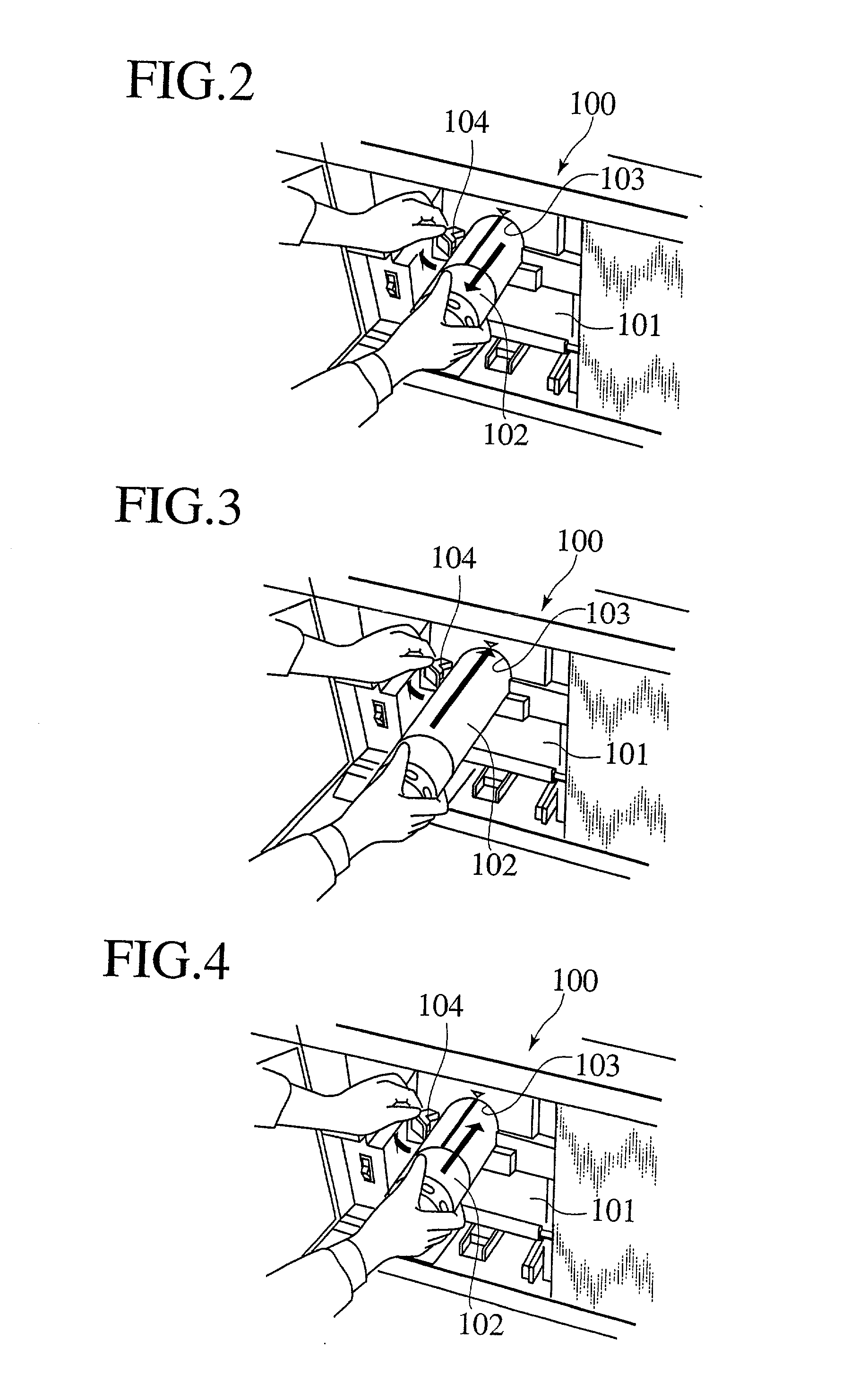
Thus, the operator must replace the ink bottle 102 using both hands, and there is a problem that the replacing operation is troublesome.
As a result of such variation, there are problems that a locking force of the ink bottle 102 by the bottle lock member 104 is lowered or the locking force is excessively increased.

Method used


Image

  • Ink bottle mounting apparatus and ink bottle for the apparatus
  • Ink bottle mounting apparatus and ink bottle for the apparatus
  • Ink bottle mounting apparatus and ink bottle for the apparatus

Examples


first embodiment

[0072] That is, if the bottle lock member 20 of the first embodiment received a constant or greater force from the bottle inserting / pulling out direction T, the bottle lock member 20 is displaced from the bottle lock position to the bottle moving permissible position against the spring force of the torsion spring 22 by this force, and if the bottle lock member 20 does not received the force, the bottle lock member 20 is automatically returned to the bottle lock position by the spring force of the torsion spring 22.

[0073] Since the bottle lock member 20 of the first embodiment is moved between the bottle lock position and the bottle moving permissible position by the spring force of the torsion spring 22, the bottle lock member 20 is not deteriorated due to the repetition of displacement, and the bottle lock member 20 is excellent in durability.

[0074] Although the torsion spring 22 is used as the biasing means for biasing the bottle lock member 20 toward the bottle moving permissible...

second embodiment

[0075] FIG. 16 shows the bottle lock member and the to-be locked portion, and is an enlarged sectional view showing a displacing state of the bottle lock member. As shown in FIG. 16, a bottle lock member 23 is made of resiliently deformable synthetic resin. A base end of the bottle lock member 23 is fixed to a bottle mounting apparatus body 11 by means of a screw 24. A leading end of the bottle lock member 23 can be displaced between the bottle lock position (solid line in FIG. 16) the bottle moving permissible position (phantom line in FIG. 16). A to-be locked portion provided on an insertion leading end of the bottle body 2 comprises a groove 5 having the same structure as that of the previous mode for carrying out the invention.

[0076] That is, if the bottle lock member 23 of the second embodiment received a constant or greater force from the bottle inserting / pulling out direction T, the bottle lock member 23 is displaced from the bottle lock position to the bottle moving permissi...

third embodiment

[0079] In this third embodiment, since both the leaf springs 25 and the groove 5 are formed into semi-arc surfaces, they can smoothly be engaged with and separated from each other.

[0080] FIG. 18 shows a fourth embodiment of the bottle lock member and the to-be locked portion, and is a sectional view showing a state in which the bottle lock member is engaged with the to-be locked portion. As shown in FIG. 18, the to-be locked portion provided on an insertion leading end of the bottle body 2 of the fourth embodiment comprises a projection 27 projecting from the side peripheral surface 2b in the form of an arc, and a free end of the bottle lock member comprises leaf springs 26 whose free ends are bent into an arc shape.


PUM


Abstract

An ink bottle mounting apparatus comprising a bottle mounting apparatus body 11 having an ink bottle 1 and a bottle insertion chamber 12 into which the ink bottle 1 is inserted, wherein the ink bottle mounting apparatus further comprises a bottle lock member 15 which is engaged with a groove 5 formed on a side peripheral surface of the ink bottle 1 to prevent the ink bottle 1 from being pulled out when the ink bottle 1 is mounted to the bottle mounting apparatus body.

Description

[0001] 1. Field of the Invention[0002] The present invention relates to an ink bottle apparatus to which an ink bottle is inserted and mounted, and an ink bottle mounted to the apparatus.[0003] 2. Description of the Related Art[0004] For example, in a stencil printing machine that is one of related art printing machine, a stencil paper of stencil printing plate is wound around a drum based on image information, a print paper is moved while bringing the paper into contact with the rotating drum under pressure, and an ink image is directly transferred to the print paper, or a transfer body is rotated and moved while bringing the transfer body into contact with the rotating drum under pressure, the ink image is once transferred to the transfer body, the print paper is moved while bringing the print paper into contact with the rotating transfer body under pressure, and the ink image is transferred to the print paper. In such a stencil printing machine, an ink bottle mounting apparatus t...

Claims


Application Information

Patent Timeline
IPC IPC(8): B41F31/02B41L13/18B41L13/14B41L27/04
CPCB41F31/02B41L13/18B41L27/04B41L13/14
Inventor SASAKI, KUNINORIWAKAYAMA, TAKAHIRO
Owner RISO KAGAKU CORP
Learn More