Method of manufacturing a disk and transfer method for the disk

a technology of transfer method and disk, which is applied in the direction of mechanical recording, recording apparatus, instruments, etc., can solve the problems of difficult to maintain flat bonded surfaces, difficult to accurately align substrates, and easy to non-uniform deformation or warpage of substrates

Inactive Publication Date: 2002-03-28
PIONEER CORP
View PDF5 Cites 7 Cited by
  • Summary
  • Abstract
  • Description
  • Claims
  • Application Information

AI Technical Summary

Benefits of technology

[0016] According to the invention, when the disk having the laminated structure is manufactured, in the fixing step, the stiffness of the first substrate is ensured to prevent occurrence of deformation or warpage and in the aligning and bonding steps, occurrence of positional displacement and eccentricity can be prevented as well as the first aspect of the invention. In addition, in the transferring step, the pit pattern is transferred to the reinforced first substrate by using the stamper. Accordingly, the pit pattern formed on the first substrate in the transferring step is accurately aligned by the reinforcement substrate. Hence, positional accuracy of an information recording surface on another layer of the disk having the laminated structure can be ensured.
[0040] According to the invention, in case that the pit pattern is transferred onto a disk having laminated structure, in the fixing step, the stiffness of the first embodiment can be ensured as well as the invention on the disk manufacturing method. In the transferring step, the pit pattern is transferred onto the reinforced first substrate by using the stamper. Hence, a high degree of positional accuracy of a pit pattern or the like formed on the first substrate in the transferring step can maintained.

Problems solved by technology

When such thin substrates are bonded together, accurate alignment of the substrates is not easy.
Since substrates are thin and have insufficient rigidity, the substrates become prone to nonuniform deformation or warpage during alignment.
Thus, sustaining bonded surfaces flat becomes difficult, thereby posing a higher risk of the substrates being bonded together with eccentricity or positional misalignment arising in a part of the substrates.

Method used


Image

  • Method of manufacturing a disk and transfer method for the disk
  • Method of manufacturing a disk and transfer method for the disk
  • Method of manufacturing a disk and transfer method for the disk

Examples


first embodiment

[0052] First Embodiment

[0053] Preferred embodiments of the present invention will be described hereinafter with reference to the accompanying drawings. There will now be described a first embodiment of manufacturing a two-layer disk having two-layer structure by means of bonding two substrates.

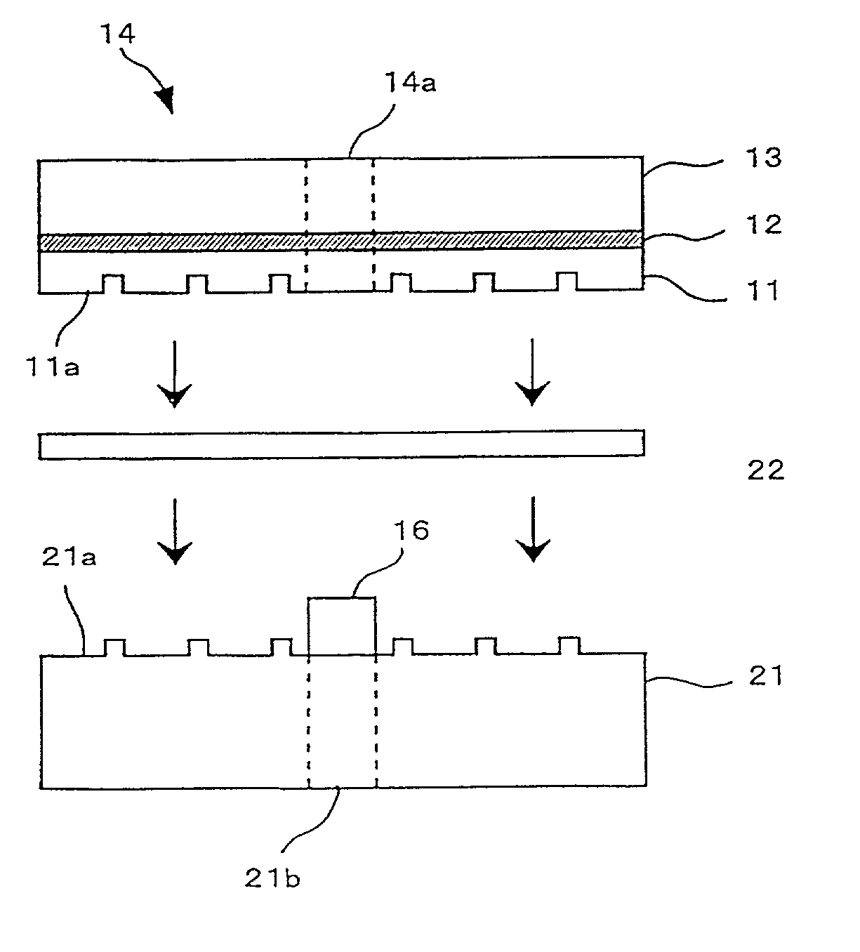
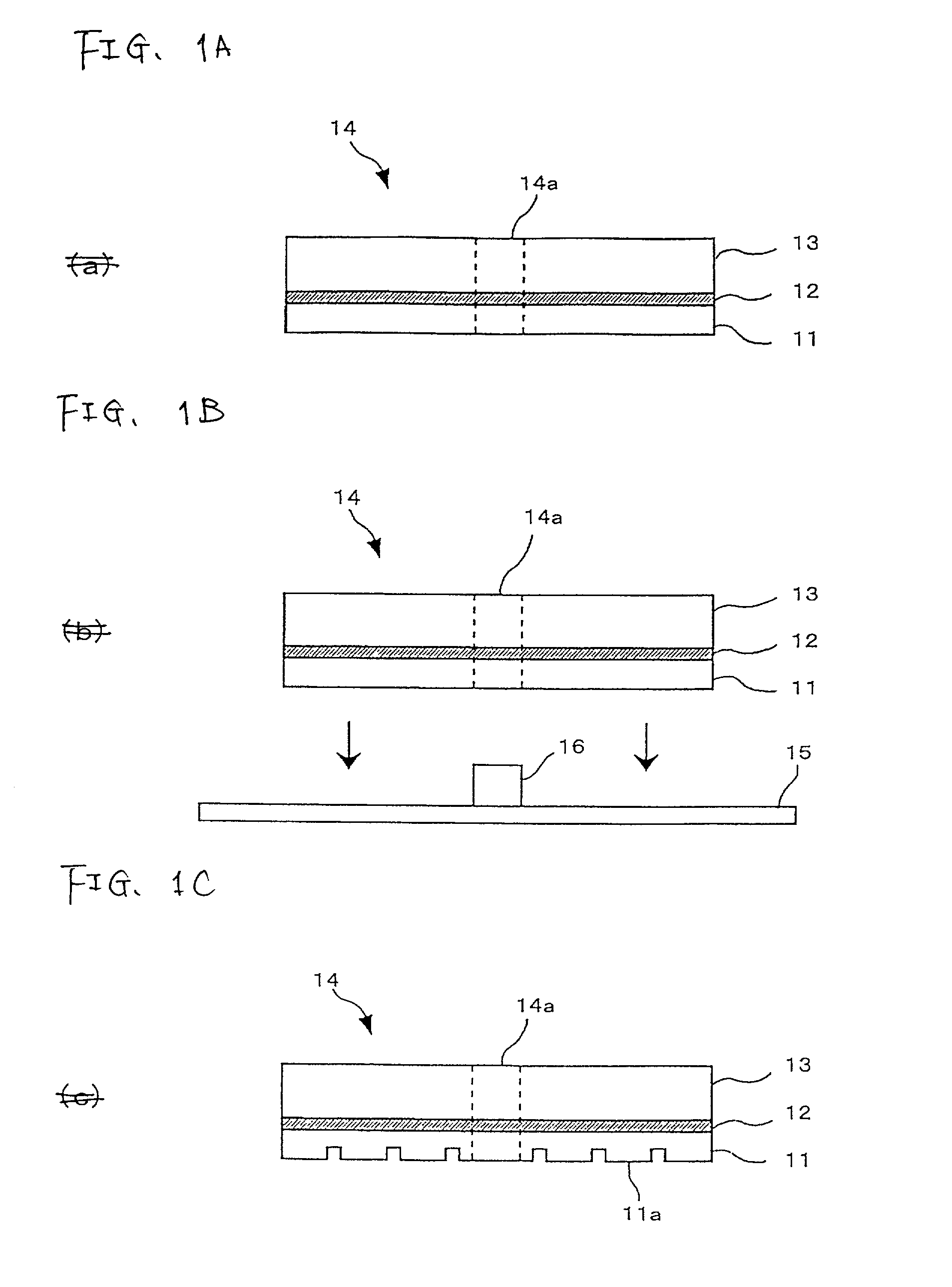
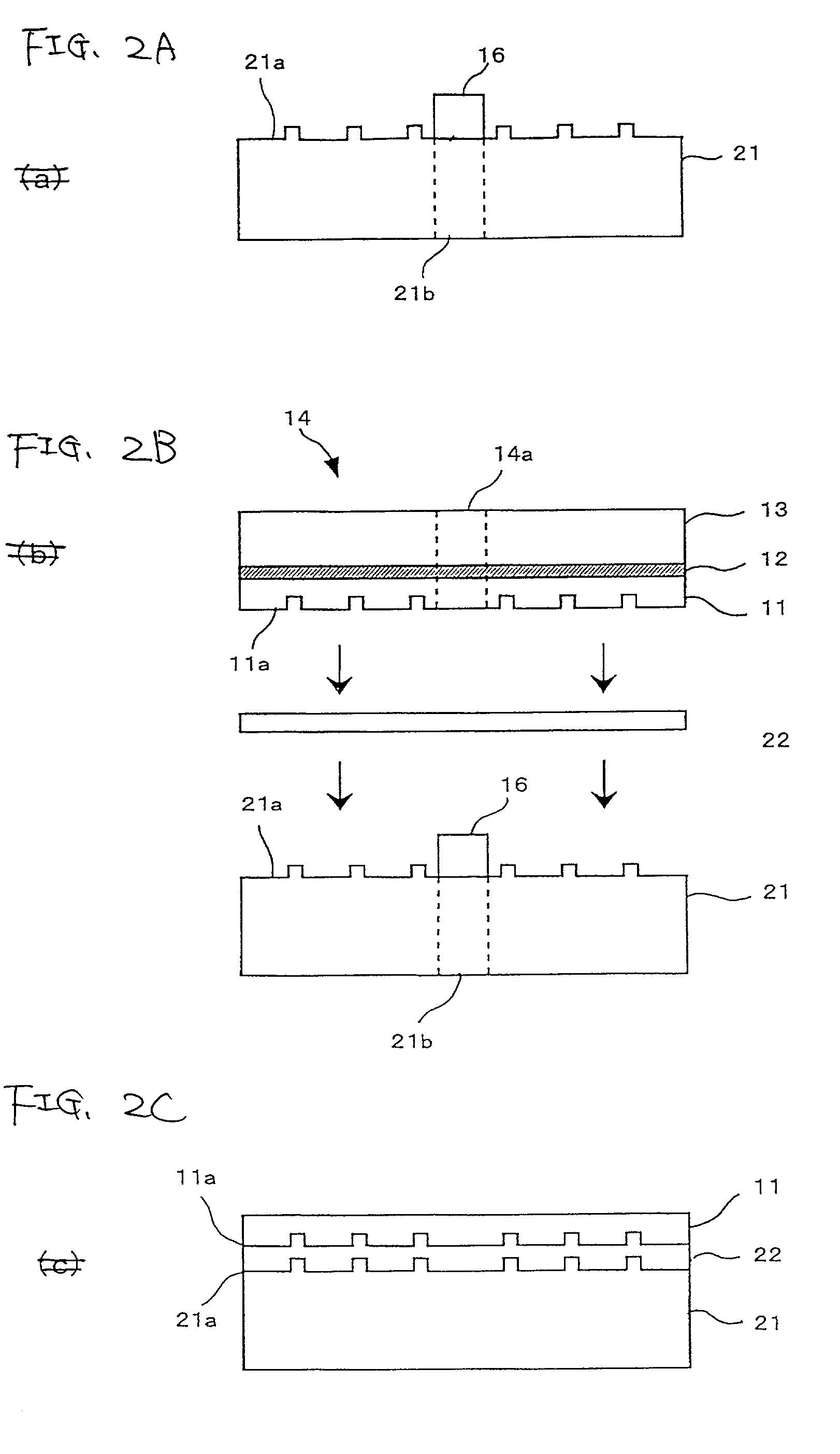
[0054] With reference to FIGS. 1A through 3C, there will be described a method of manufacturing a two-layer disk according to a first embodiment. FIGS. 1A through 1C are illustrations for describing, in the method of manufacturing a two-layer disk according to the first embodiment, a reinforcement process for bonding a glass layer to a cover layer to reinforce the cover layer and a transfer process for transferring a signal recording surface to a cover layer.

[0055] As shown in FIG. 1A, in the reinforcement process, there is prepared a cover layer 11 as a first substrate for acting as a first layer of the two-layer disk. The cover layer 11 is made of, e.g., an acrylic material, and has a thickn...

second embodiment

[0081] Second Embodiment

[0082] A second embodiment of the present invention will be described. The second embodiment differs from the first embodiment in that a transfer process is to be performed before a reinforcement process.

[0083] FIGS. 5A through 5D are illustrations for describing, in a method of manufacturing a two-layer disk according to the second embodiment, processes corresponding to those shown in FIGS. 1 of the first embodiment. First, as shown in FIG. 5A, the cover layer 11 is prepared. Subsequently, in contrast with the case of FIG. 1, processing proceeds to a transfer process without carrying out the reinforcement process at this step.

[0084] As shown in FIG. 5B, in the transfer process, the cover layer 11 is subject to transfer by using the stamper 15. While the cover layer 11 is aligned with the center boss 16 with a state where the center hole of the stamper 15 is set to the center boss 16, the cover layer 11 is integrated with and pressed to the stamper 15 to perf...

third embodiment

[0087] Third Embodiment

[0088] A third embodiment of the present invention will be described. The third embodiment differs from the first embodiment in that a two-layer disk is manufactured in the disk bonding process in consideration of positional accuracy in a periphery direction of a disk.

[0089] In the third embodiment, a shape of the glass substrate 13 differs from that of the glass substrate 13 according to the first embodiment so that alignment in the peripheral direction of the disk is performed in the bonding process. FIG. 6 is an illustration showing a structure of the bonded substrate 14 according to the third embodiment, in which the cover layer 11 and the glass substrate 13 are integrated together. FIG. 6A is a view of the bonded substrate 14 when viewed from the same side as that in FIG. 1A, and FIG. 6B is a view of the bonded substrate 14 when viewed in direction B of FIG. 6A.

[0090] As shown in FIG. 6A, the bonded substrate 14 according to the third embodiment has the g...


PUM

PropertyMeasurementUnit
thicknessaaaaaaaaaa
diameteraaaaaaaaaa
thicknessaaaaaaaaaa

Abstract

In case of manufacturing a disk having a two-layer structure, a glass substrate 13 is bonded to a cover layer 11 through an adhesive layer 12, and a mount hole 14a is formed in a center thereof to form a bonded substrate 14 having a three-layer structure (a). In a state where a stamper 15 formed a predetermined pit pattern is set to a center boss 16, the bonded substrate 14 is pressed downward in a vertical direction while the mount hole 14a of the bonded substrate 14 is aligned with the center boss 16(b). Whereby an information recording surface 11a is transferred onto the cover layer 11(c). Subsequently, after the bonded substrate 14 has been bonded to another layer substrate of the disk, the adhesive layer 12 is removed to separate the glass substrate 13. Finally, there is manufactured the disk having the two-layer structure.

Description

[0001] 1. Filed of the Invention[0002] The present invention relates to a method of manufacturing a disk, such as a DVD, and more particularly, to a technical field pertaining to a method of manufacturing a disk by means of bonding together substrates, each having formed therein pits and grooves carrying recorded information.[0003] 2. Description of the Related Art[0004] Demand for a further improvement in recording density has recently existed for disks such as DVDs, and attention has been paid to a multilayer disk having a bonded structure of information recording surfaces of disks. For example, in case of a two-layer disk, two substrates for bonding purpose, each having an information recording surface, are manufactured separately. An intermediate bonding layer made of an adhesive is provided on one of the substrates which remains stationary. The other substrate is aligned and stacked onto the intermediate bonding layer, thereby constituting a two-layer disk. In connection with s...

Claims


Application Information

Patent Timeline
Patent Type & Authority Applications(United States)
IPC IPC(8): B29C65/76B29C65/78G11B7/26
CPCB29C65/76B29C65/78B29C65/7802B29C65/7811B29C65/7841B29C66/472B29L2017/005G11B7/26B29C65/7855B29C66/452B29C65/00B29C66/1122B29C66/71B29K2069/00
Inventor SHIDA, NORIYOSHISUGA, KEIJI
Owner PIONEER CORP
Why Eureka
Try Eureka