Active noise attenuation system

Inactive Publication Date: 2002-04-04
3840620 CANADA
View PDF8 Cites 3 Cited by
  • Summary
  • Abstract
  • Description
  • Claims
  • Application Information

AI Technical Summary

Benefits of technology

0013] The subject apparatus provides a simple method for assembling an active noise attenuation syst

Problems solved by technology

Engine noise is propagated through the air induction systems, which is undesirable.
This connection orientation results in a time consuming and diffi

Method used


Image

  • Active noise attenuation system
  • Active noise attenuation system
  • Active noise attenuation system

Examples


Embodiment Construction

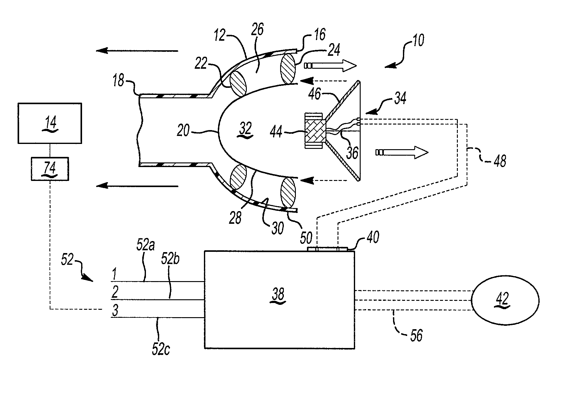
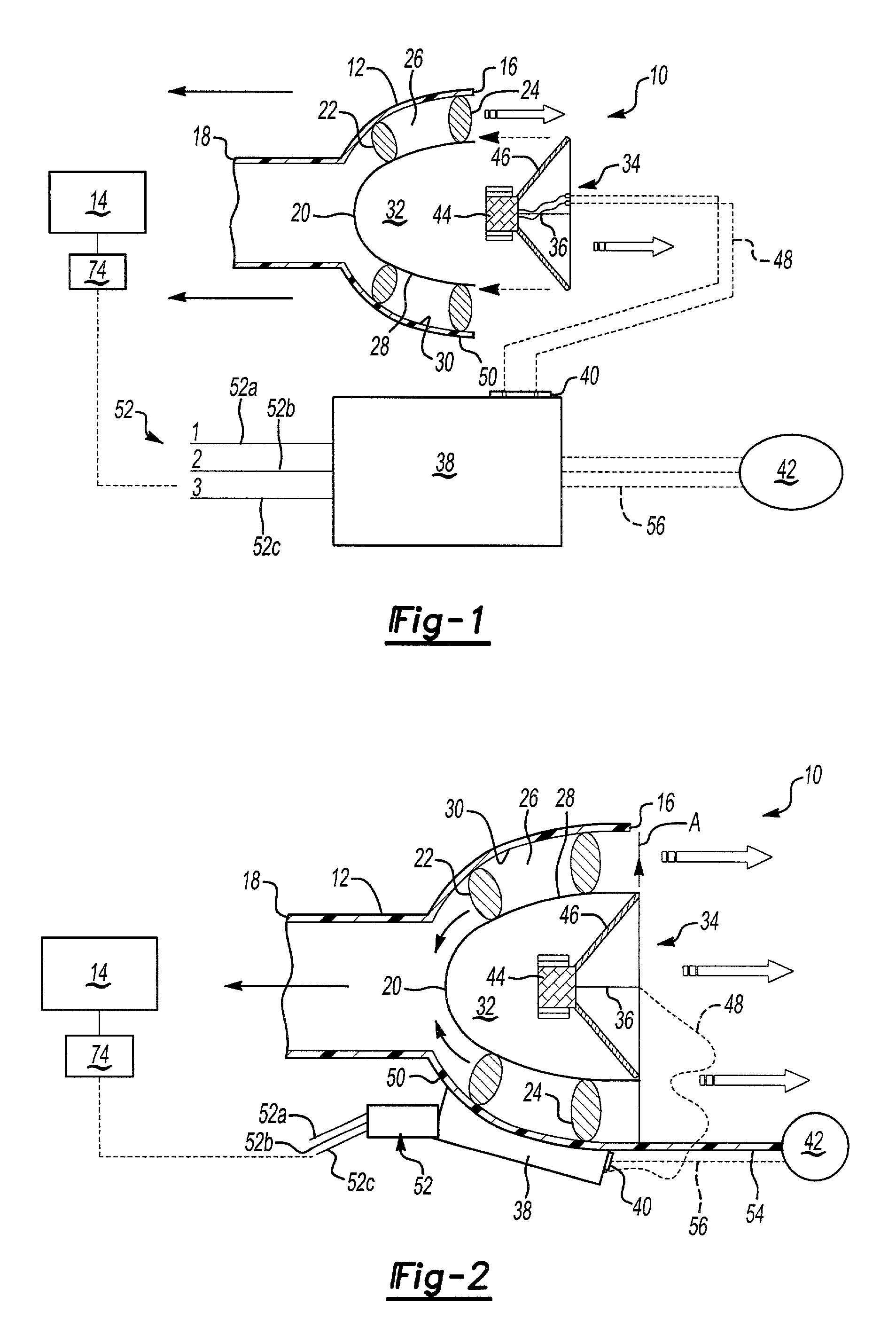
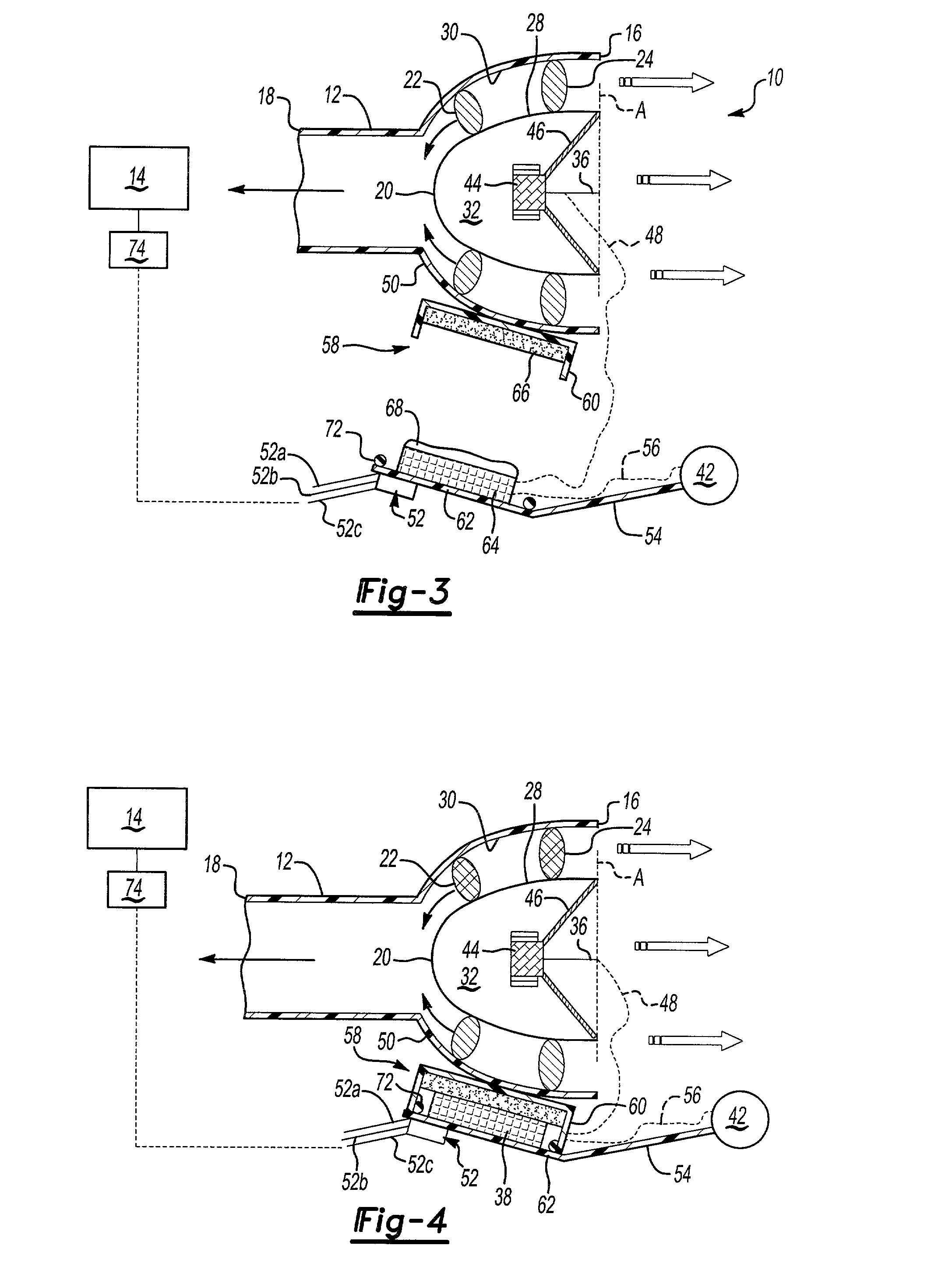
[0020] Referring to the drawings, FIG. 1 shows a noise attenuation system 10 including an air inlet duct housing 12 forming part of an air induction system for an internal combustion engine 14. The air inlet duct housing 12 has an open forvard facing end 16 and a rearward end 18 that faces the engine 14. The forward facing end 16 is of greater diameter than the rearward end 18.

[0021] Mounted within the air inlet duct housing 12 is a mid-body portion 20. The mid-body portion 20 is concentrically positioned within air inlet duct housing 12 on a pair of integrally formed struts 22, 24 to define an annular passage 26 between an exterior surface 28 of the mid-body portion 20 and an interior surface 30 of the air inlet duct housing 12. The mid-body portion 20 is preferably parabola shaped to define a central chamber 32 with a tapered bottom end facing the engine 14 and an open end facing away from the engine 14.

[0022] A speaker assembly 34 is mounted within the chamber 32 and includes a s...


PUM


Abstract

An active noise attenuation system for an air induction assembly includes a housing that is mounted to a vehicle structure and a speaker assembly that is mounted within the housing to generate a sound field for attenuating noise. The housing defines an air inlet duct open end through which air is drawn. A microphone detects noise and modifies an anti-noise signal that is sent from an electronics center. The electronics center receives the signal, mixes with other engine signals, phase-shifts the signal, and sends the phase-shifted signal to the speaker to attenuate the noise. The speaker includes electrical connections that extend outwardly toward the air inlet duct open end for connection to the electronics center. The microphone and speaker are connected to the electronics center with flex cables.

Description

[0001] This application claims priority to provisional application 60 / 193,225 filed on mar. 30, 2000.[0002] 1. Field of the Invention[0003] This invention relates to a method and apparatus for assembling an active noise attenuation system for an air induction system. Specifically, a speaker is assembled into a housing and includes front facing electrical connectors for connection to a controller.[0004] 2. Related Art[0005] Internal combustion engines include air induction systems for conducting air to engine cylinders. Engine noise is propagated through the air induction systems, which is undesirable. Noise attenuation mechanisms have been installed within the air induction systems to reduce these noises. Typically these noise attenuation mechanisms include a speaker, a microphone. and a signal generator that are mounted within an air inlet duct housing. The microphone detects the noise and generates a noise signal that is sent to the signal generator. The signal generator phase-shi...

Claims


Application Information

Patent Timeline
IPC IPC(8): F02M35/04F02M35/12F02M35/14
CPCF02M35/021F02M35/04F02M35/125F02M35/14F02M35/10373
Inventor DALY, PAUL D.
Owner 3840620 CANADA
Why Eureka
Try Eureka