Process and apparatus for electrocoagulative treatment of industrial waste water

Inactive Publication Date: 2002-04-11
UNITED RENTALS NORTH AMERICA INC
View PDF0 Cites 46 Cited by
  • Summary
  • Abstract
  • Description
  • Claims
  • Application Information

AI Technical Summary

Benefits of technology

0013] It is an object of the present invention to provide for an electroco

Problems solved by technology

However, the cell is constructed so as to be particularly difficult to disassemble for inspection and repair.
This device is cylindrical in form, makes use of a single, centrally-disposed electrode for operation, and is very difficu

Method used


Image

  • Process and apparatus for electrocoagulative treatment of industrial waste water
  • Process and apparatus for electrocoagulative treatment of industrial waste water
  • Process and apparatus for electrocoagulative treatment of industrial waste water

Examples


Embodiment Construction

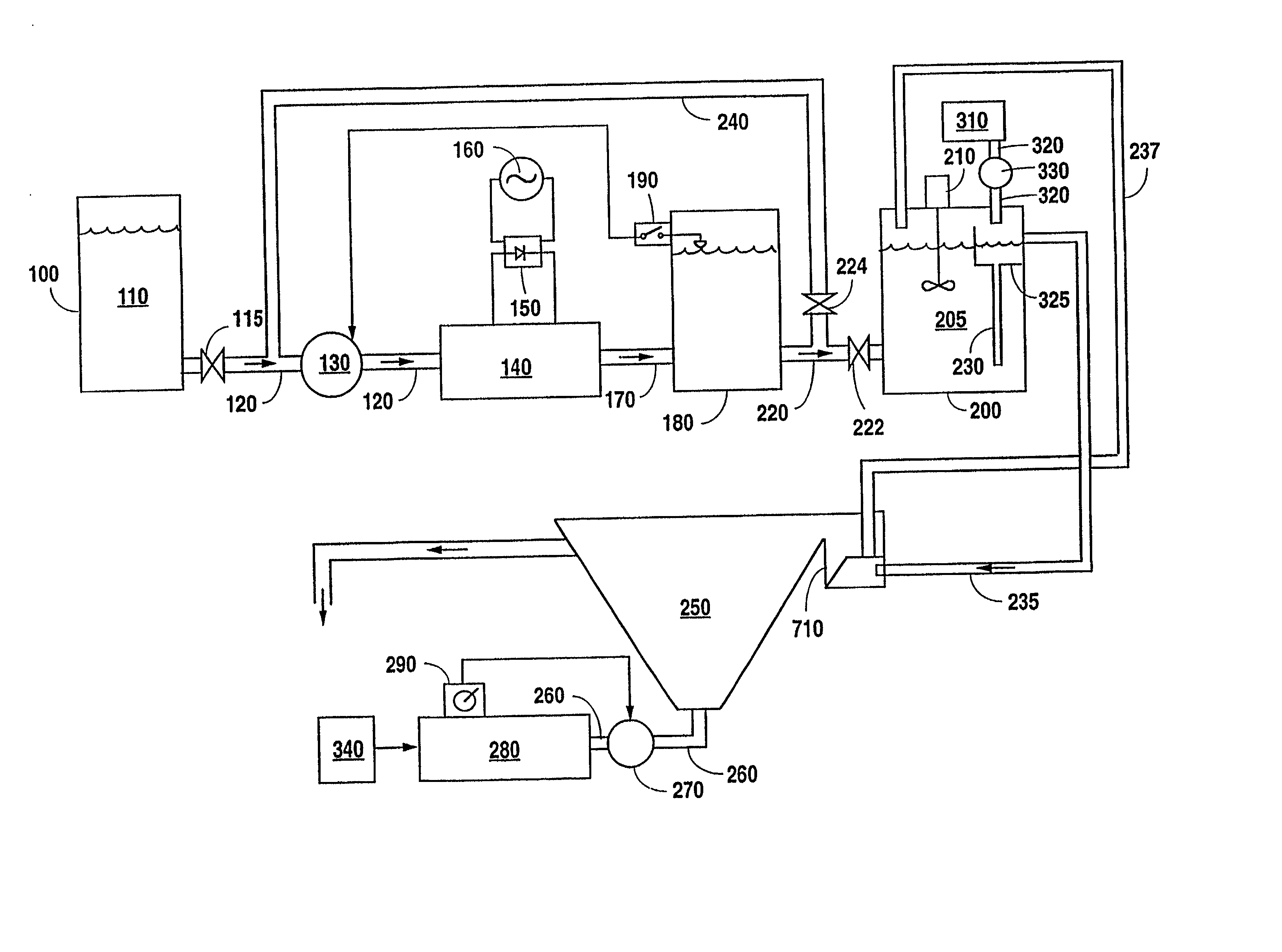
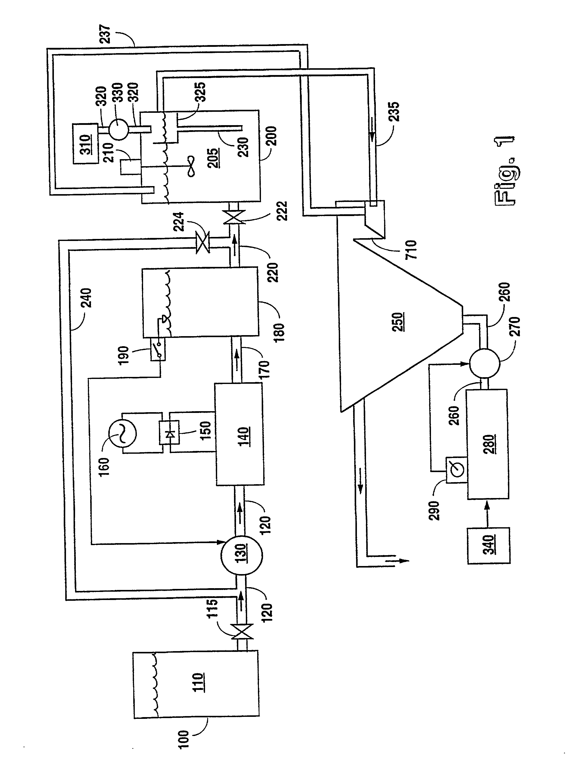
[0061] Turning now to FIG. 1, it can be seen that waste water 110 is pumped from a waste holding tank 100 by way of holding tank valve 115 (which must be open), waste water pump 130, and waste pipe 120 into electrocoagulation reactor unit 140. Waste water 110 may also be taken directly out of another process (not shown), as it is produced, instead of from waste holding tank 100. Pump 130, which is typically a diaphragm-type, low-pressure, low volume unit, is configured to operate at a pressure such that a constant volume of waste water 110 per time interval is moved into the inlet of reactor unit 140.

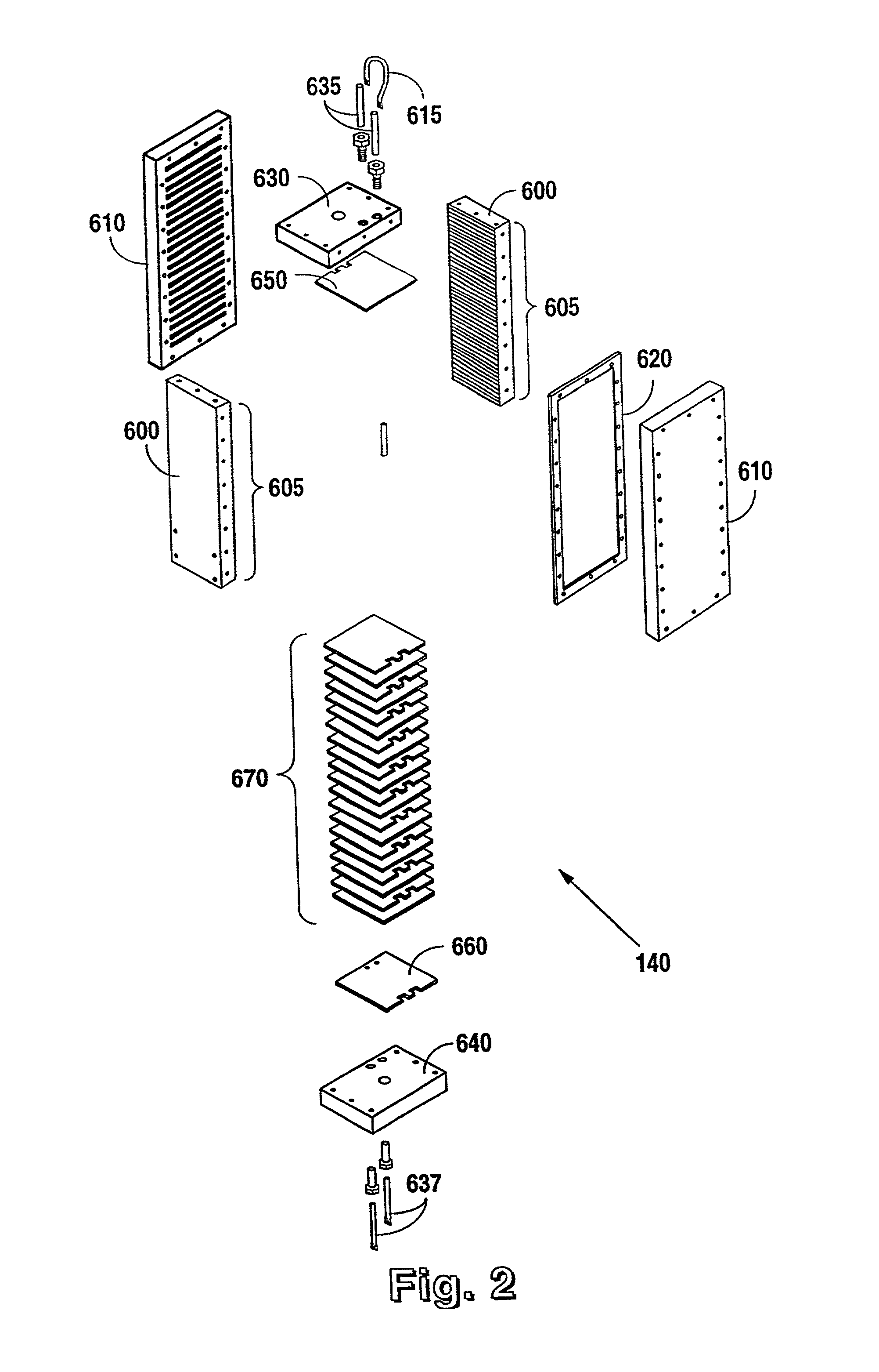
[0062] Reactor unit 140 may comprise a single electrocoagulation reactor cell, or as a series of such cells, depending on the amount and composition of particulate waste present in waste water 110. The more waste which is present, the more efficiently multiple cells, operating as a series-connected fluid path, can be employed. Rectifier 150 takes alternating current from an appropriate ...


PUM

PropertyMeasurementUnit
Pressureaaaaaaaaaa
Flow rateaaaaaaaaaa

Abstract

An electrocoagulation system for removing contaminants from waste effluents comprising an electrocoagulation reactor having charged and uncharged plates and allowing serial flow of water therethrough. The reactor is connected to a voltage source to charge some of the plates positive and some negative, with uncharged plates between the positive and negative plates. The system allows waste water to enter the reactor for coagulation therein, the waste water leaving the reactor to enter a defoam tank for agitation which allows trapped bubbles to rise to the surface of the tank as foam. From the defoam tank, waste water goes through a sludge thickener, to allow sludge to settle at the bottom thereof and waste water is drawn off from the sludge thickener to flow to a clarifier. The pump removes sludge forming at the bottom of clarifier to take it back to the sludge thickener. The sludge is drawn out the bottom of the sludge thickener for transport to a press where most of the water is removed therefrom. Water is drawn off the top of the clarifier for transport to a conventional sewer system, or for reuse.

Description

BACKGROUND OF THE INVENTION[0001] 1. Field of the Invention[0002] The present invention relates to a process for the treatment of industrial waste water by electrolysis and, more particularly, for cleaning industrial waste water recovered, for example, from industrial boilers, or otherwise containing contaminants, utilizing an electrocoagulative process to chemically bond with a particle to change the particle from in solution to in suspension which can be flocculated and separated from the water. The invention also relates to an apparatus for carrying out the process and especially to an electrolytic cell sludge thickener bubble pump and clarifier used for that purpose.[0003] 2. Description of the Related Art[0004] The present invention is directed to improving processes and apparatuses for removing impurities from fluids in a manner which is safe, economical, and user friendly. Attempts by others to provide improvements in the art of water purification are represented by the inven...

Claims


Application Information

Patent Timeline
IPC IPC(8): C02F1/463
CPCC02F1/463
Inventor MORKOVSKY, PAUL E.KASPAR, DOUGLAS D.
Owner UNITED RENTALS NORTH AMERICA INC
Why Eureka
Try Eureka