Method and apparatus in a production line

a production line and method technology, applied in the manufacture of final products, instruments, manufacturing tools, etc., can solve the problems of affecting the quality of finished products, and requiring very small tolerance limits, and often creating bulges around the edges of the holes of coating materials

Inactive Publication Date: 2002-04-18
TELEFON AB LM ERICSSON (PUBL)
View PDF0 Cites 10 Cited by
  • Summary
  • Abstract
  • Description
  • Claims
  • Application Information

AI Technical Summary

Problems solved by technology

If the position of a hole deviates more than 0.1 mm, the screw may not engage in a receiving thread and it may also damage the heavy components, the printed board and/or the element as it is forced downwards by the screw machine.
The insertion of a guide pin in one of the corresponding holes in the element is often done manually and the guide pin is secured to the hole by a press fit, which demands very small limits of tolerance for the contacting surfaces of the guide pin and the wall of the hole in the element.
This coating material often creates bulges around the edges between the holes for the guide pins and the surface, as well as bulges inside the holes.
Therefore, small limits of tolerance for the guide pins and the corresponding holes in the element generate higher fabrication costs than guide pins and holes with larger limits of tolerance.
Also, the manual insertion makes great demands upon a worker when inserting a guide pin, since the press fit easily gives a slight inclination from the desired guide direction of the guide pin.
The inclination might cause inaccurate positioning of the printed board assembly, which makes it even more diffi

Method used


Image

  • Method and apparatus in a production line
  • Method and apparatus in a production line
  • Method and apparatus in a production line

Examples


Embodiment Construction

[0036] While the invention covers various modifications and alternative constructions, preferred embodiments of the invention are shown in the drawings and will hereinafter be described in detail. It is to be understood, however, that the specific description and drawings are not intended to limit the invention to the specific forms disclosed. On the contrary, it is intended that the scope of the claimed invention includes all modifications and alternative constructions thereof falling within the spirit and scope of the invention as expressed in the appended claims to the full range of their equivalents.

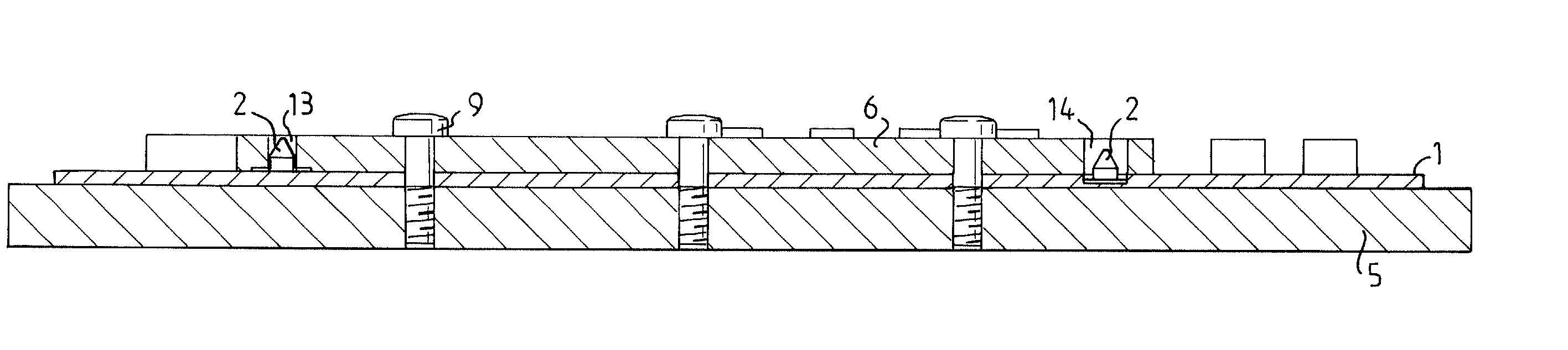
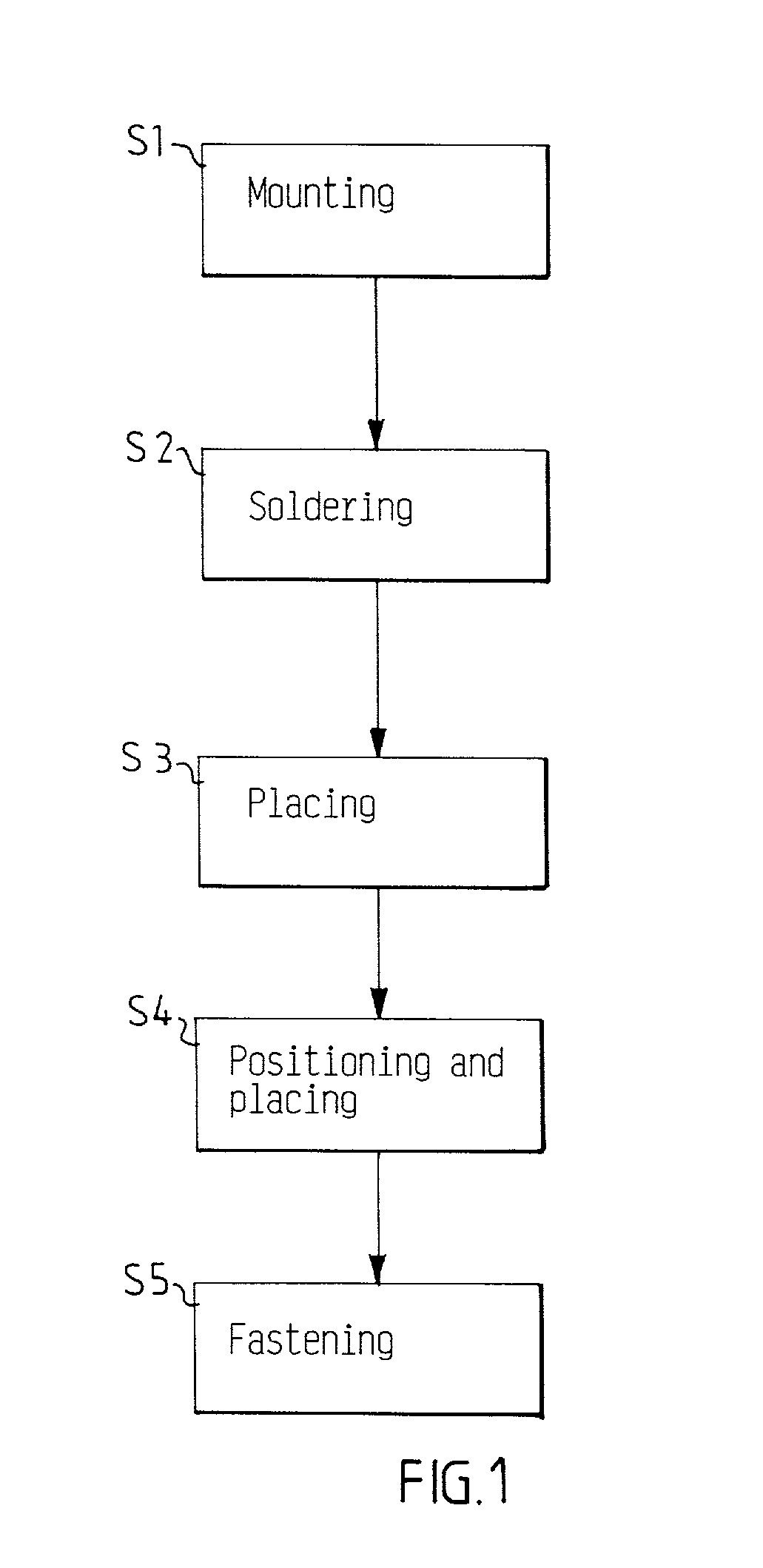
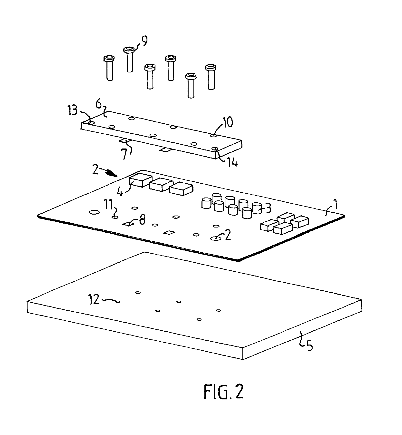
[0037] FIG. 1 shows a schematic block diagram of a preferred method for mounting a electronic or mechanical component to a printed board, where the method is divided into five principal steps S1-S5. Before the first step, a printed board 1 has been fabricated and a solder paste has been applied to at least one side of the printed board 1. Such a method is known in the prior art and i...


PUM

PropertyMeasurementUnit
Timeaaaaaaaaaa
Shapeaaaaaaaaaa

Abstract

The invention relates to a method for mounting at least one electronic or mechanical component on a printed board comprising the steps of: surface-mounting at least one guide element on the printed board or placing the at least one guide element in a dead end hole in the printed board, fastening the at least one guide element to the printed board by soldering before guiding the at least one electronic or mechanical component towards the printed board, and placing the at least one electronic or mechanical component on the printed board with the help of the at least one guide element. The invention also relates to a guide element and a electronic or mechanical component to be used in the method.

Description

[0001] The present invention relates to a method for mounting electronic and / or mechanical components on a printed board, a guide element and an electronic or mechanical component.DESCRIPTION OF RELATED ART[0002] For the purpose of this patent application, the term `electronic component` is used for any electric or electronic components, such as capacitors, resistors, transistors and integrated circuit chips that could be mounted to a printed board to create a printed board assembly. Examples of component included in the term `mechanical components` are shields, housings and supports for the shields.[0003] The assembly process for an apparatus that comprises a printed board assembly involves several automatic assembly steps and often also at least some manual assembly steps. One of the assembly steps is to mount standard electronic components, and sometimes mechanical components, on a printed board. This is often done by applying a soldering paste on the printed board and automatica...

Claims


Application Information

Patent Timeline
IPC IPC(8): H05K3/30H05K3/34H05K7/14
CPCH05K3/303H05K3/341H05K7/142H05K2201/10409H05K2201/10598Y10T29/4913Y10T29/49004Y10T29/53174Y10T29/49165Y10T29/49117Y10T29/49126H05K2203/167Y02P70/50
Inventor JANSSON, ULF
Owner TELEFON AB LM ERICSSON (PUBL)
Why Eureka
Try Eureka