

Roller type test stand for testing motor vehicles and/or tires
- Summary
- Abstract
- Description
- Claims
- Application Information
AI Technical Summary
Benefits of technology
Problems solved by technology
Method used
Image

Examples
Embodiment Construction
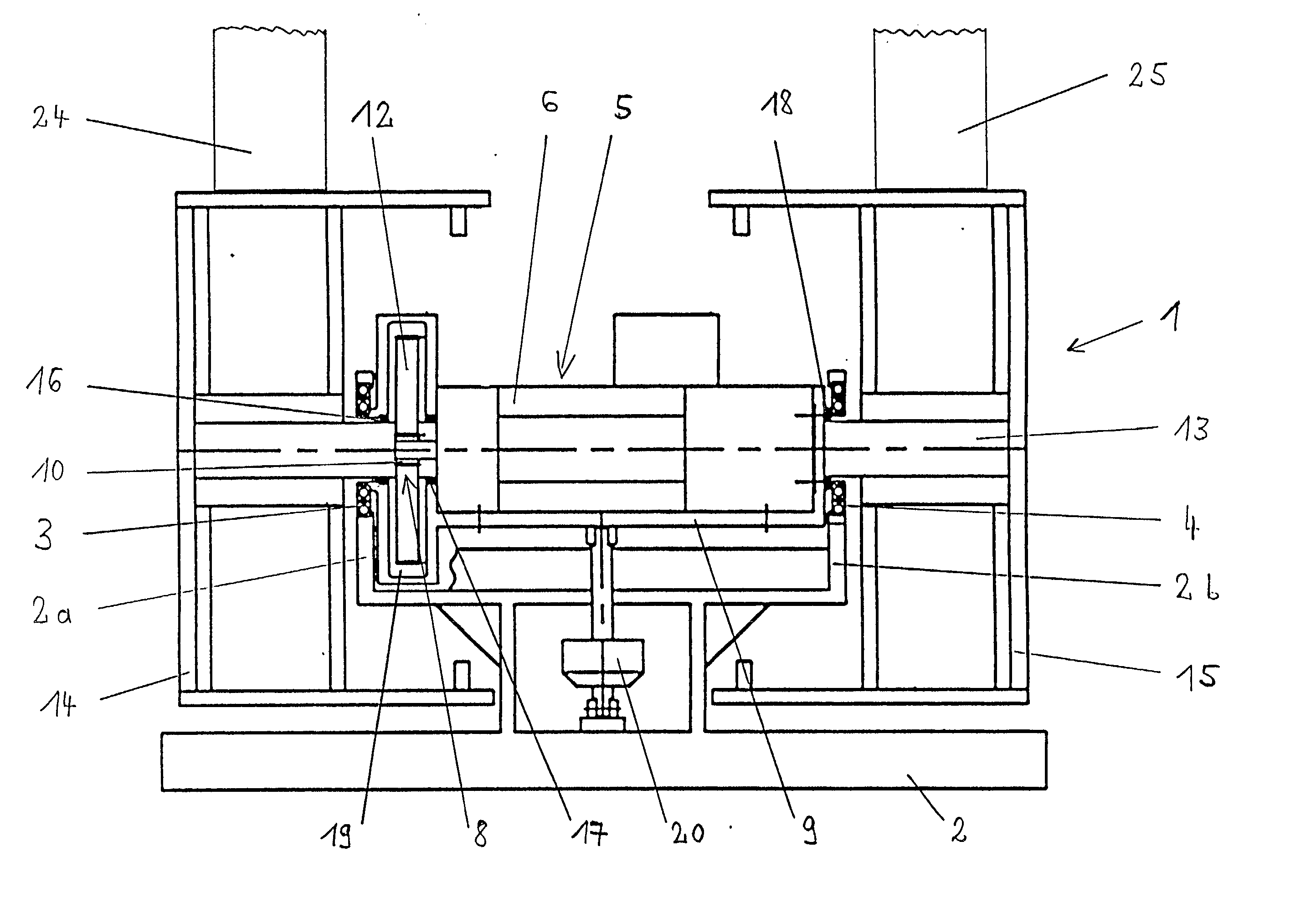
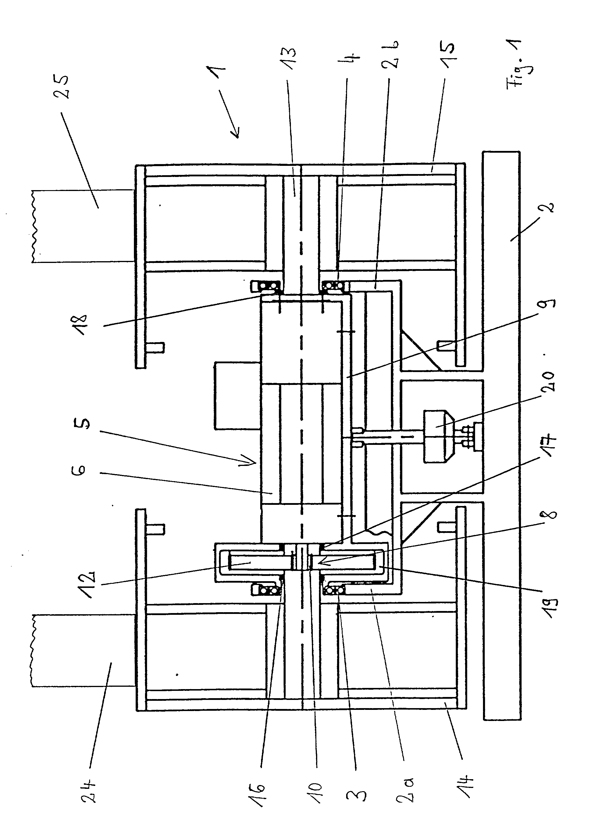
[0026] Referring now to FIG. 1a side view of a roller type test stand 1 according to the present invention is shown. The roller type test stand 1 comprises a supporting frame 2 and supporting arms 2a, 2b arranged thereon. A motor / transmission combination 5 is swing mounted between the supporting arms 2a, 2b by bearing elements 3, 4.
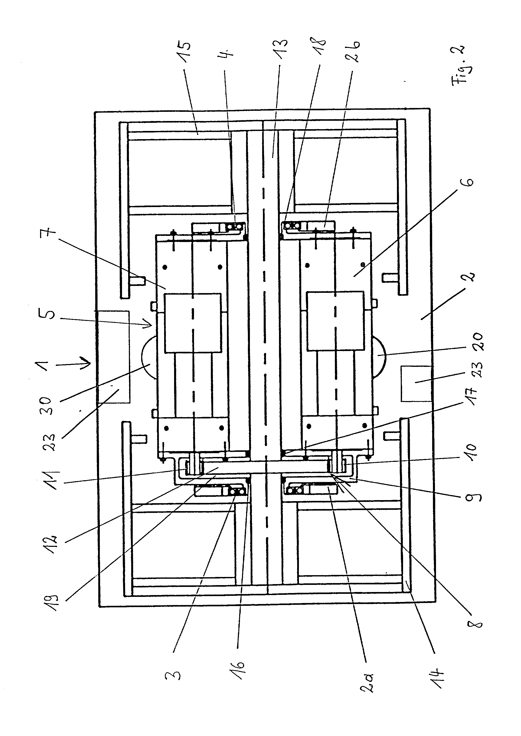
[0027] Referring now to FIG. 2, a plan view of the present invention is shown. The motor / transmission combination 5 comprises a first motor 6, a further motor 7, a transmission 8 and a frame 9. An electric motor and / or a hydraulic motor is provided as the motor 6, 7.
[0028] The transmission 8 comprises two pinions 10, 11, which are arranged directly on the motors 6, 7, and a gearwheel 12, which meshes with the pinions 10, 11. The gearwheel 12 is arranged on a shaft 13. Running rollers 14, 15 are arranged at both ends of the shaft 13.
[0029] The shaft 13 is mounted on the frame 9 by means of bearing elements 16, 17, 18. The motors 6, 7 are also mounted on th...
PUM
| Property | Measurement | Unit |
|---|---|---|
| tensile forces | aaaaa | aaaaa |
| resistance | aaaaa | aaaaa |
| constant volume flow | aaaaa | aaaaa |
Abstract
Description
Claims
Application Information