
Insulation of stator windings with shrink-on sleeves

Inactive Publication Date: 2002-04-25
ALSTOM TECH LTD
View PDF16 Cites 21 Cited by
  • Summary
  • Abstract
  • Description
  • Claims
  • Application Information

AI Technical Summary

Benefits of technology

[0015] It was found to be advantageous that the shrink-on sleeve is mechanically dilated in its cold state and applied to the outer periphery of a support device, in particular, a support sleeve, before the support sleeve that has been surrounded with the shrink-on sleeve is pulled over the conductor bar, whereby the support sleeve is larger than the conductor in order to facilitate the application of the shrink-on sleeve onto the conductor bar.
[0021] A preferred mechanical connection between the conductor bar and the shrink-on sleeve can be achieved if the shrink-on sleeve has at its contact surfaces with the conductor bar a thermally stable adhesive. This also prevents the formation of voids, so that the thermal conductivity is improved and electrical void discharges are avoided, which is especially an advantage for variations in which no internal corona shielding is used.
[0022] If the shrink-on sleeve is constructed of an extruded elastomer sleeve, it can be constructed continuously, on the one hand, in an advantageous manner, and, on the other hand, can be adjusted to different bar geometries. The elastomer insulation furthermore prevents tearing of the insulation during the bending. The present invention uses the high elasticity of the elastomer while maintaining the ability to withstand high thermal and electrical stresses. For higher thermal stresses a silicone elastomer is used advantageously.
[0023] In a particularly preferred method, the conductor bars are only brought into their final shape after being encased with the elastomer. The bending of the involutes greatly stretches the applied insulation. The use of elastomer according to the invention is hereby found to be particularly advantageous, since it reduces or even completely avoids mechanical, electrical or thermal injury to the insulation that is being stressed by bending.

Problems solved by technology

The insulations of stator windings that have been applied by winding have the disadvantage that their manufacture is time- and cost-intensive.
This manufacturing process is particularly prone to defects especially in the case of thick insulations, if the mica paper adapts insufficiently to the stator winding.
In particular, an insufficient adjustment of the winding machine after wrapping the stator winding may result in wrinkles and tears in the mica paper, for example, because of a too steep or flat angle between the mica paper and the conductor, or because of an unsuitable static or dynamic tensile force acting on the mica paper during the wrapping.
An excessive tape application may also result in overlaps that prevent uniform impregnation of the insulation in the impregnation tool.
This may create a locally or generally defective insulation with reduced short-term or long-term stability.
This significantly reduces the life span of such insulations for stator windings.
But such shrink-on techniques cannot be used for stator windings with a rectangular cross-section since the sleeves with their round cross-section easily tear along the edges of the rectangular conductors, either immediately after shrinking or after being strained briefly while the electrical machine is operated, because of the thermal and mechanical stresses.
Even while the stator windings are being manufactured, especially during the bending and handling of the conductors, particularly during installation into the stator, the insulation must be able to bear a significant high mechanical stress which could damage the insulation of the stator windings.
This results both in a shearing stress of the bond between conductor and insulation and a risk of abrasion at the interface between insulation and slot wall of the stator.
Because of these high stresses, the insulation of the stator windings may tear, resulting in a short circuit.
Consequently, the entire electrical machine will fail, and the repair will be time- and cost-intensive.

Method used


Image

  • Insulation of stator windings with shrink-on sleeves
  • Insulation of stator windings with shrink-on sleeves
  • Insulation of stator windings with shrink-on sleeves

Examples


Embodiment Construction

[0011] This is the starting point for the invention. The invention, as characterized in the claims, is based on the objective of creating a process for insulating stator windings for rotating electrical machines, whereby insulated stator windings are produced that ensure the insulation of the stator winding over the intended life span of the electrical machine.

[0012] This objective is realized by the method according to the characteristics of independent claim 1.

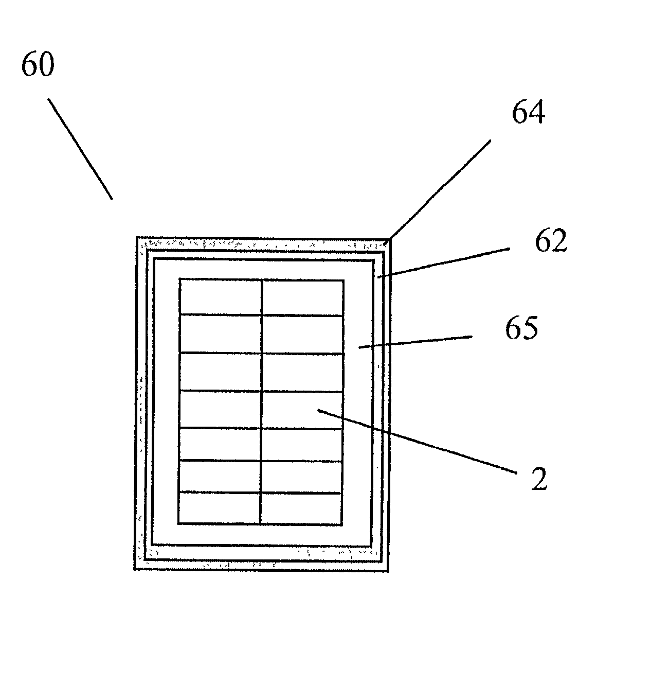
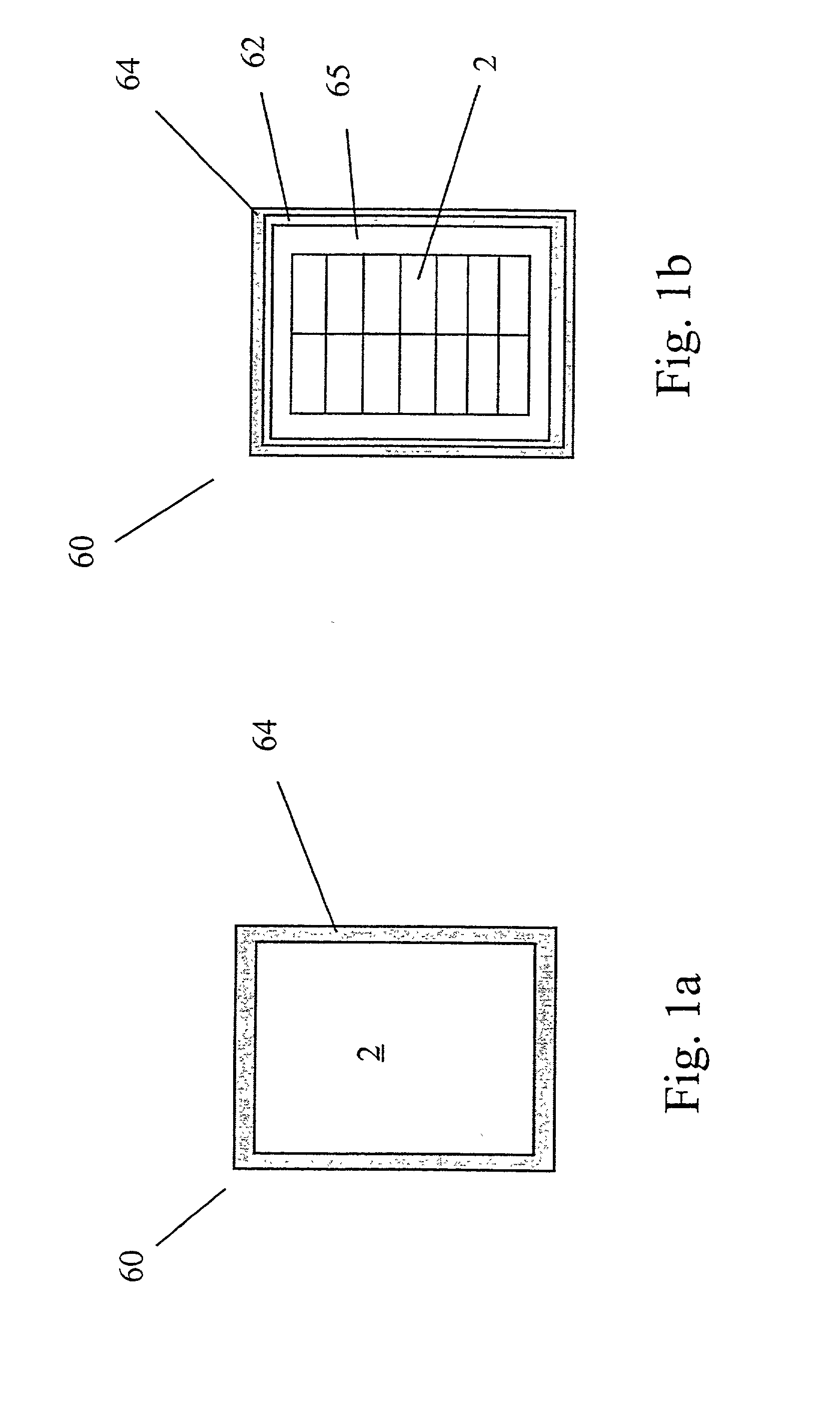
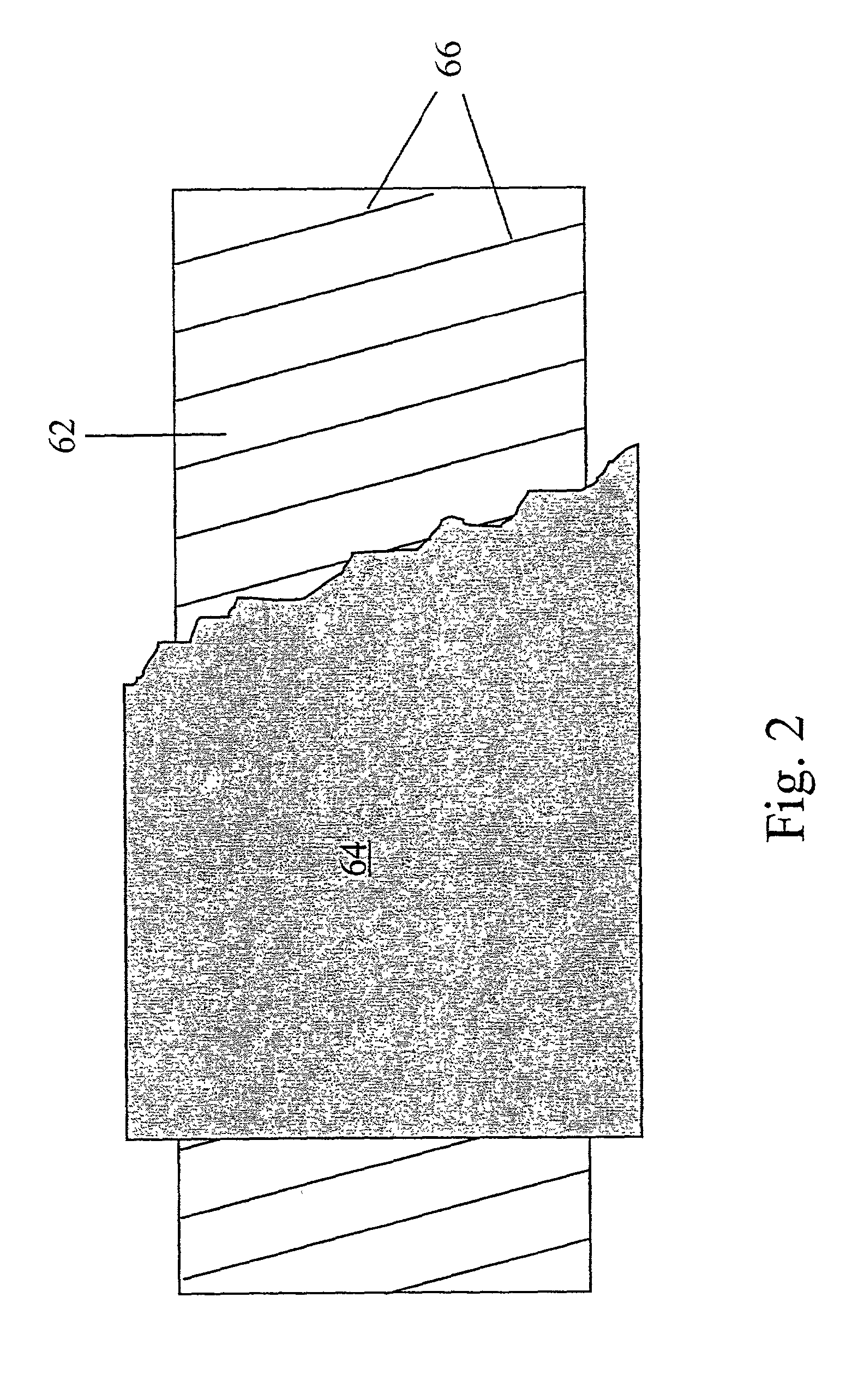
[0013] The method according to the invention for producing an insulated stator winding for rotating electrical machines, in particular, direct current machines and alternating current machines, where said insulated stator winding is constructed of at least one electrically conductive conductor bar with an essentially rectangular cross-section, whereby at least one electrically insulating shrink-on sleeve with an essentially rectangular cross-section is applied to the periphery of the conductor bar and shrunk onto the conduct...


PUM


Abstract

Described is a method for the production of an insulated stator winding for rotating electrical machines, in particular, direct current machines and alternating current machines, whereby an insulated stator winding is produced that ensures adequate insulation over the intended life span of the electrical machine. The insulated stator winding is constructed of at least one electrically conductive conductor bar (2) with an essentially rectangular cross-section, whereby at least one electrically insulating shrink-on sleeve (64) with an essentially rectangular cross-section is applied to the periphery of the conductor bar (2) and then shrunk onto it.

Description

FIELD OF TECHNOLOGY[0001] The invention relates to a method for insulating stator windings for rotating electrical machines, in particular, direct current machines and alternating current machines.STATE OF THE ART[0002] In general, such electrical machines are provided with a stator and a rotor in order to convert mechanical energy into electrical energy (i.e., a generator) or, vice versa, to convert electrical energy into mechanical energy (i.e., an electric motor). Depending on the operating status of the electrical machine, voltages are generated in the conductors of the stator windings. This means that the conductors of the stator windings must be appropriately insulated in order to avoid a short circuit.[0003] Stator windings in electrical machines can be constructed in different ways. It is possible to bundle several individual conductors that are insulated against one another and to provide the conductor bundle created in this manner, often called a conductor bar, with a so-c...

Claims


Application Information

Patent Timeline
IPC IPC(8): H01B7/02H01F5/06H01B17/58H02K3/04H02K3/32H02K3/34H02K15/04H02K15/10
CPCH02K3/345
Inventor BAUMANN, THOMASOESTERHELD, JOERGGASPARINI, RICO
Owner ALSTOM TECH LTD
Learn More