
Motor

a technology of motors and bearings, applied in the field of motors, can solve problems such as the worsening of the rotation precision of the motors

Inactive Publication Date: 2002-04-25
NSK LTD
View PDF0 Cites 11 Cited by
  • Summary
  • Abstract
  • Description
  • Claims
  • Application Information

AI Technical Summary

Benefits of technology

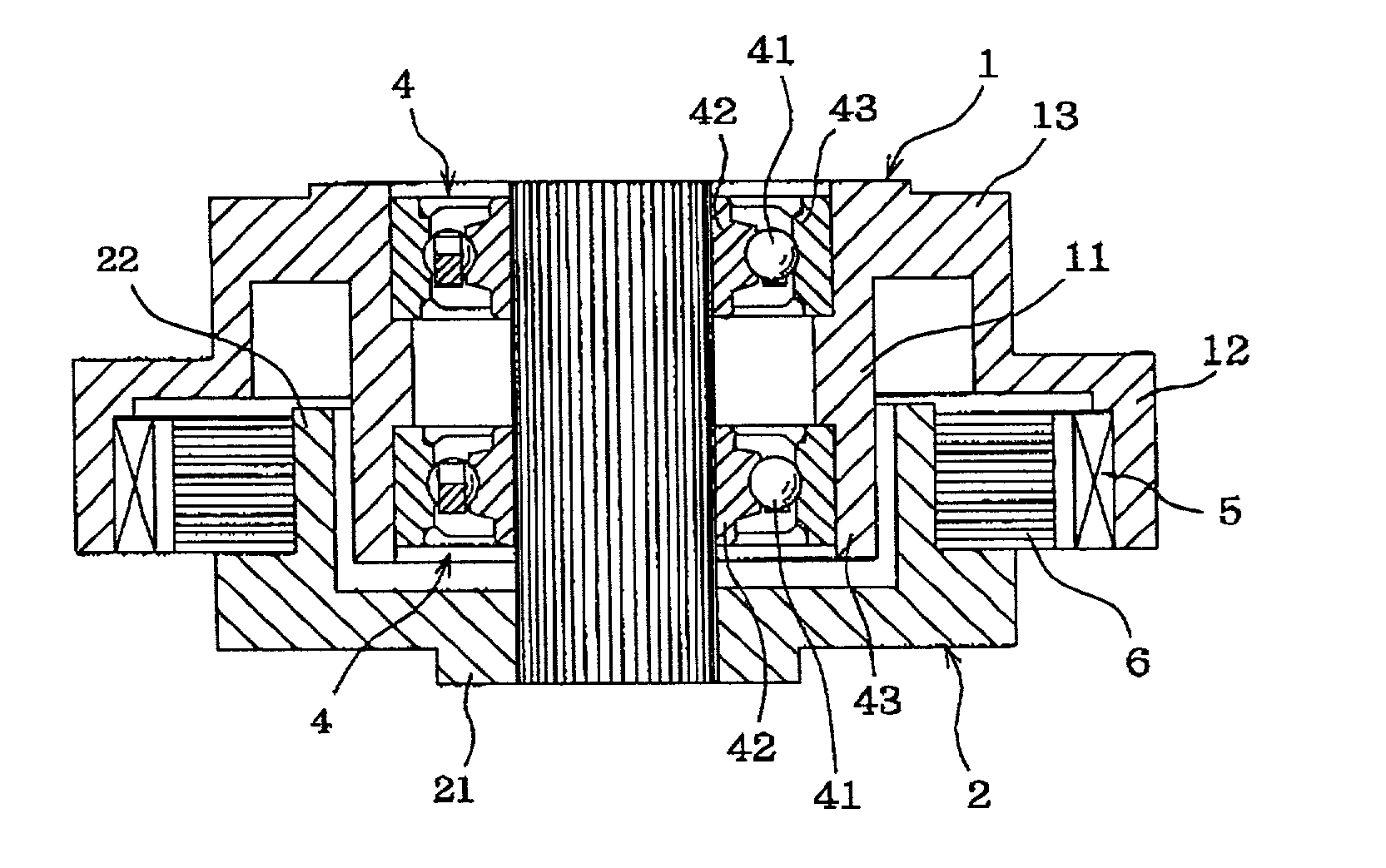
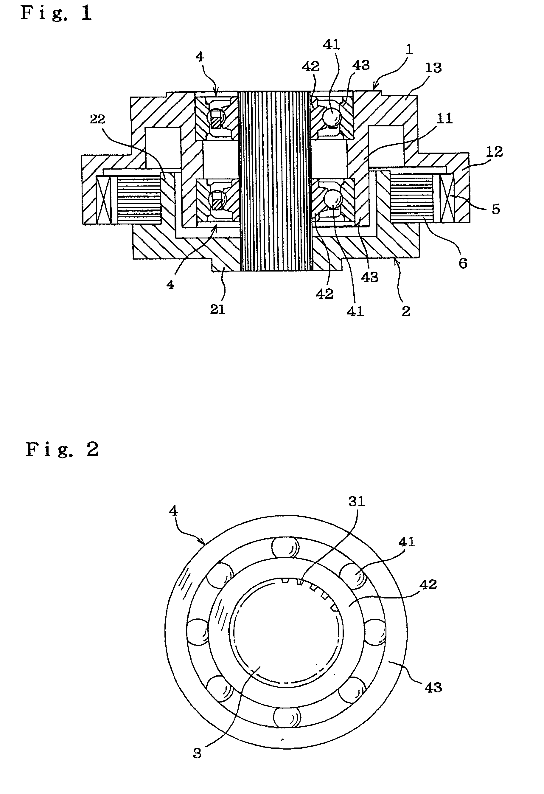
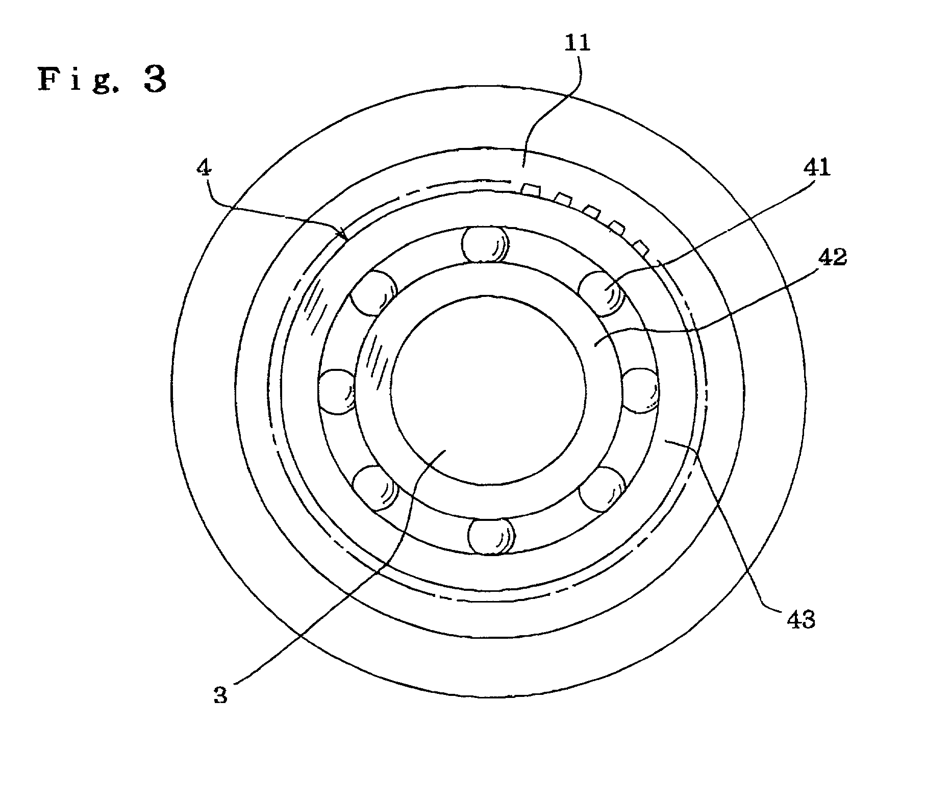
The present invention provides a motor with a rolling bearing between a housing and a shaft, where the inner and outer races of the rolling bearing are fixed to the shaft and the housing, respectively, through press-fitting or adhesion with the grooves formed in the outer surface of the shaft and the inner surface of the housing. The technical effect of this invention is to prevent deformation of the races and improve the rotation precision of the motor, by reducing the unevenness of the expansion and shrinkage forces of the adhesive used to fix the races. Additionally, the patent text describes the use of knurled grooves on the shaft and housing to further improve the precision of the motor.

Problems solved by technology

As a result, the expansion and shrinkage forces of the adhesive may be so uneven in the circumferential direction that the races are deformed and that the rotation precision of the motor is worsened.

Method used


Image

  • Motor
  • Motor
  • Motor

Examples


Embodiment Construction

[0013] The present invention provides a motor comprising a rotor, a Stator and a shaft, wherein the stator or rotor is provided with a housing, and a rolling bearing is provided between the housing and the shaft, and wherein the inner race and the outer race of the rolling bearing are fixed to the shaft and the housing, respectively, through press-fitting or through adhesion with the grooves formed in the outer peripheral surface of the shaft and in the inner peripheral surface of the housing.

[0014] Specifically, in one feature of the motor of the present invention, the outer peripheral surface of the shaft and / or the inner peripheral surface of the housing are formed with knurled grooves, and wherein the number (P) of the grooves in the circumferential direction and the number (Z) of the rolling members in the rolling bearing are in the relations of Pn p Z and PnZ.+-.1 where n is a positive integer.

[0015] In another feature of the motor, specifically the outer peripheral surface of...


PUM


Abstract

A motor comprises a rotor, a stator, and a shaft wherein one of the stator and the rotor is provided with a housing, a rolling bearing is provided between the housing and the shaft and having an inner race and outer race, the inner race is fixed to the shaft through adhesion between the outer peripheral surface of the shaft and the inner peripheral surface of the inner race, the outer race is fixed to the housing through press-fitting, and the outer peripheral surface of the shaft is formed with knurled grooves, where the number (P) of the knurled grooves in the circumferential direction and the number (Z) of the rolling members in the rolling bearing are in the relations of P≢n Z and P≢nZ±1 where n is a positive integer.

Description

[0001] 1. Field of the Invention[0002] The present invention is related to a motor for use in office automation devices such as the magnetic hard disc drive device (HDD), video tape recorder (VTR) and laser beam printer (LBP).[0003] 2. Related Art of the Invention[0004] The motor for the OA devices generally comprises a rotor with a magnet fixed to it and a stator with a coil fixed to it. The rotor or stator is provided with a housing, and a rolling bearing is provided between the housing and a shaft.[0005] Conventionally, an adhesive is used to fix the rolling bearing between the shaft and the housing in the OA devices. For example, in order that the inner race is fixed to the shaft, a groove is formed around the shaft, and the adhesive is provided between the groove and the inner peripheral surface of the inner race, so that the uniform bonding is made in the circumferential direction.[0006] According to the publication of JP Patent No. 2890159, the outer peripheral surface of the...

Claims


Application Information

Patent Timeline
Patent Type & Authority Applications(United States)
IPC IPC(8): F16C35/063F16C35/067H02K5/173H02K5/24
CPCF16C35/067F16C35/0635H02K5/1737F16C19/06F16C19/54F16C2226/40
Inventor AOKI, MAMORUMIYAGAWA, TAKAYUKIISHIWADA, HIROSHI
Owner NSK LTD
Learn More