Method and device for the reduction of load cycle oscillations in the drive train of a motor vehicle

Inactive Publication Date: 2002-04-25
ZF FRIEDRICHSHAFEN AG
View PDF1 Cites 17 Cited by
  • Summary
  • Abstract
  • Description
  • Claims
  • Application Information

AI Technical Summary

Problems solved by technology

In a known solution, a particularly slow torque change takes place.
The disadvantage of this solution, however, is that the vehicle reacts too sluggishly and experiences a considerable loss of dynamics.
In this known method, however

Method used


Image

  • Method and device for the reduction of load cycle oscillations in the drive train of a motor vehicle
  • Method and device for the reduction of load cycle oscillations in the drive train of a motor vehicle
  • Method and device for the reduction of load cycle oscillations in the drive train of a motor vehicle

Examples


Embodiment Construction

[0049] The same reference symbols in the various figures relate to essentially identical or functionally identical elements or values.

[0050] The invention is described below first by means of the load cycle driving condition, reference being made to FIGS. 1 to 8b.

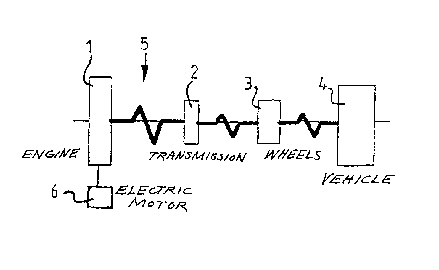
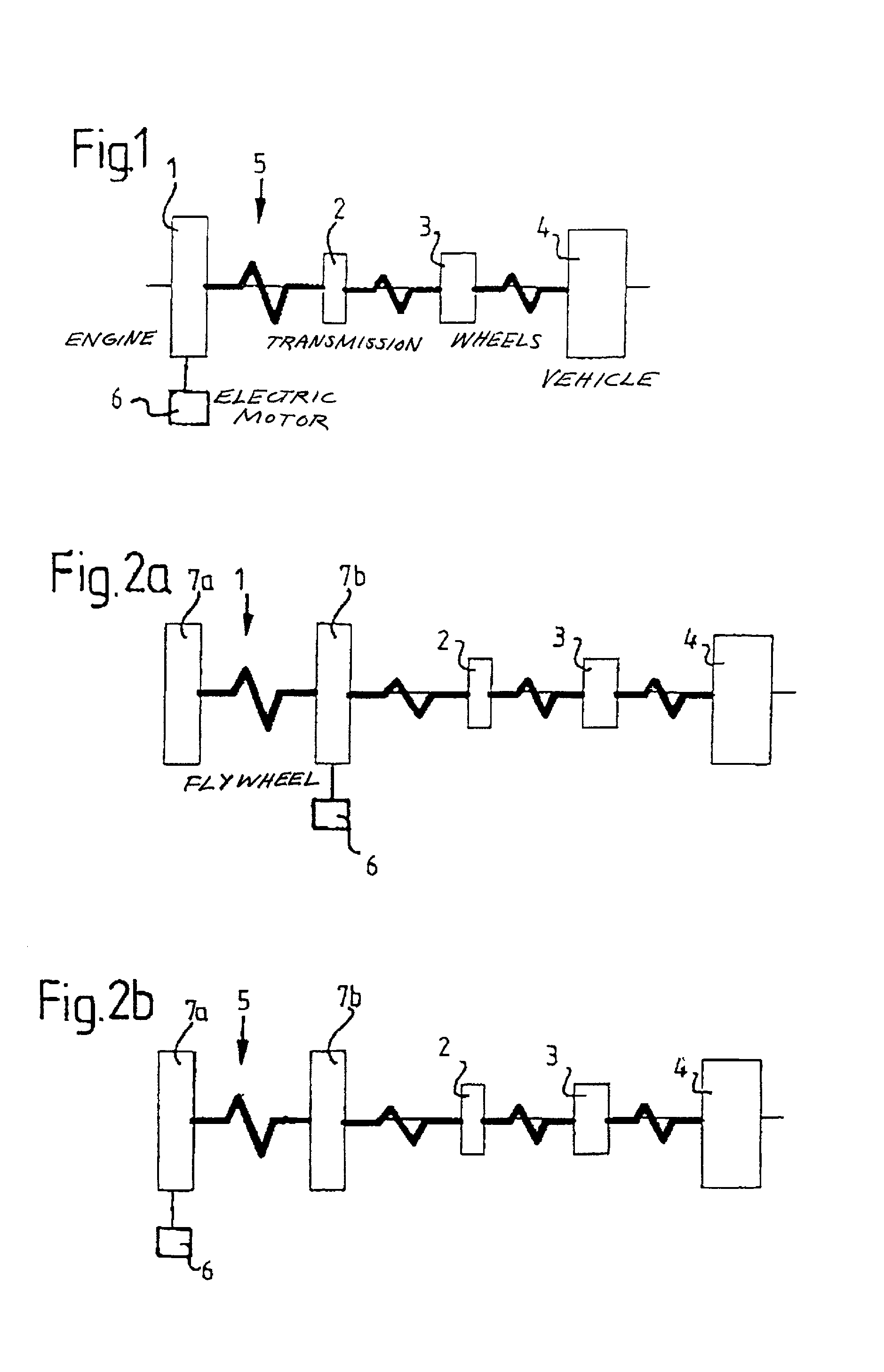
[0051] FIG. 1 shows a diagrammatic illustration of a block diagram of a drive train for the load cycle driving condition, that is to say with the clutch engaged. An engine 1 or an internal combustion engine is coupled to a transmission 2 which, in turn, is coupled to wheels 3 of a vehicle 4 in order to drive the latter. A torsion damper 5, such as is generally known, is inserted between the engine 1 and the transmission 2. An electric motor 6 serves for applying an additional torque pulse from outside. The electric motor 6 is coupled to the engine 1.

[0052] FIG. 2a shows another embodiment of the invention for the load cycle driving condition, but in the case of an engine with a two-mass flywheel. A primary part 7a and a sec...


PUM


Abstract

Load cycle oscillations in the drive train of a motor vehicle are reduced by detecting a change in available torque in the drive train, determining the period of a load cycle oscillation, and, at the commencement of the available torque change, applying at least one additional torque pulse, which causes an oscillation in phase opposition to the load cycle oscillation and which lasts half the period of the load cycle oscillation.

Description

[0001] 1. Field of the Invention[0002] The present invention relates to a method for the reduction of load cycle oscillations in the drive train of a motor vehicle which includes detecting a change in available torque in the drive train of a motor vehicle, and determining the period of a load cycle oscillation which is caused by a change in the useful torque. The invention also relates to a device for the reduction of load cycle oscillations in the drive train of a motor vehicle.[0003] 2. Description of the Related Art[0004] Changing transmission torques occur in drive trains of vehicles in different driving conditions. A change in the driving condition of a vehicle or motor vehicle, for example an acceleration, requires a change in the drive torque generated by the vehicle engine. Since the drive train of a motor vehicle comprises various masses and elasticities, the drive train of the motor vehicle is excited to load cycle oscillations as a result of this torque change or of this ...

Claims


Application Information

Patent Timeline
IPC IPC(8): F02N11/00B60W10/06B60W10/08F02D29/00F02D29/02F02D41/10F02D41/14F16F15/02F16F15/31
CPCB60W10/06B60W10/08B60W30/20F02D41/10F02D2250/28F02D2200/1002F02D2200/1012F02D2250/21F02D2250/24F02D41/1497
Inventor TEBBE, GERHARD
Owner ZF FRIEDRICHSHAFEN AG
Why Eureka
Try Eureka