End-to-side blood vessel anastomosis method and instruments therefor

a blood vessel and end-to-side technology, applied in the field of end-to-side blood vessel anastomosis method and instruments therefor, can solve the problems of high patient stress, blood vessel dissection with tweezers or the like, and difficult to carry out anastomosis of coronary artery bypass graft,

Inactive Publication Date: 2002-04-25
TERUMO KK
View PDF6 Cites 27 Cited by
  • Summary
  • Abstract
  • Description
  • Claims
  • Application Information

AI Technical Summary

Problems solved by technology

In particular, anastomosis of coronary artery bypass graft, which is carried out on blood vessels that are very thin and under a narrow field of vision, is very difficult to carry out.
However, the blood vessel of which anastomosis is needed usually is hardened and very brittle because of calcification or the like so that there is the fear that the blood vessel when clipped with tweezers or the like could be torn at the dissected portion.
However, use of a pump-oxygenator gives much stress on patients.
In the bypass graft under heart beating, the surface of the heart moves due to the heartbeat, which makes the blood vessel anastomosis more difficult.
This procedure itself is difficult as described above.
When they are in contact with the blood flow, they are recognized as foreign matter, leading to the possibility of thrombus formation.

Method used


Image

  • End-to-side blood vessel anastomosis method and instruments therefor
  • End-to-side blood vessel anastomosis method and instruments therefor
  • End-to-side blood vessel anastomosis method and instruments therefor

Examples


first embodiment

[0083] First Embodiment

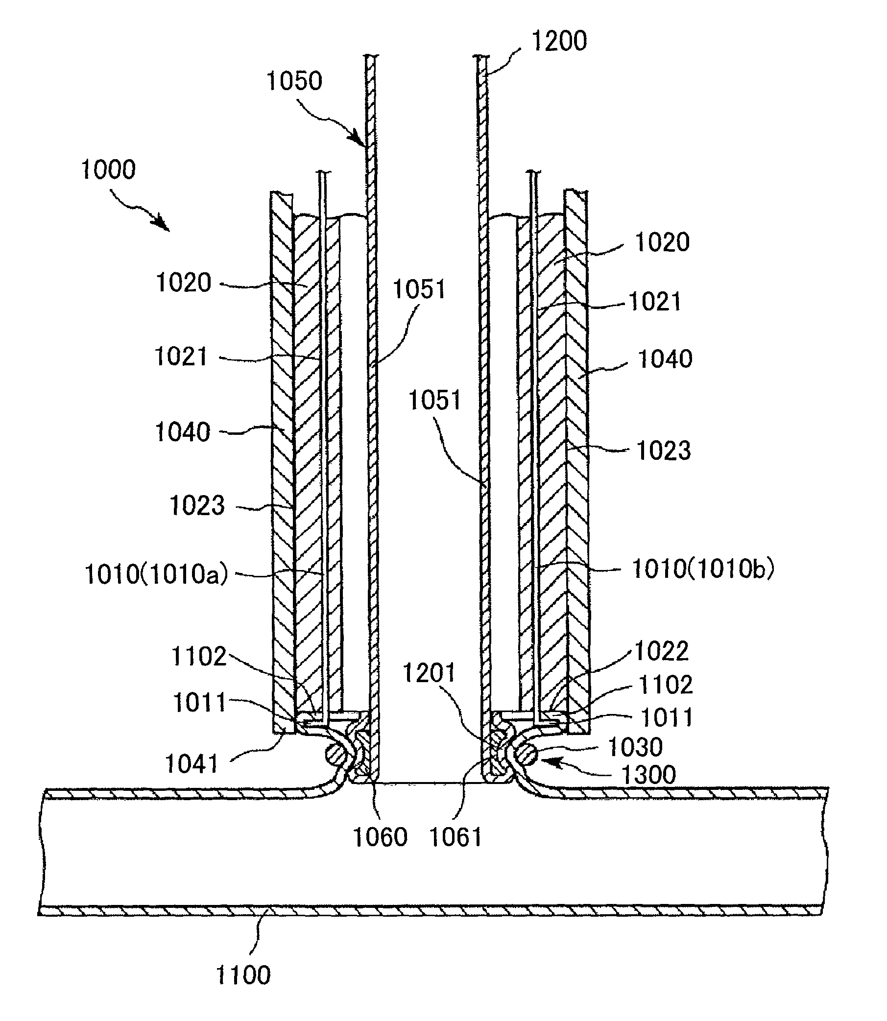
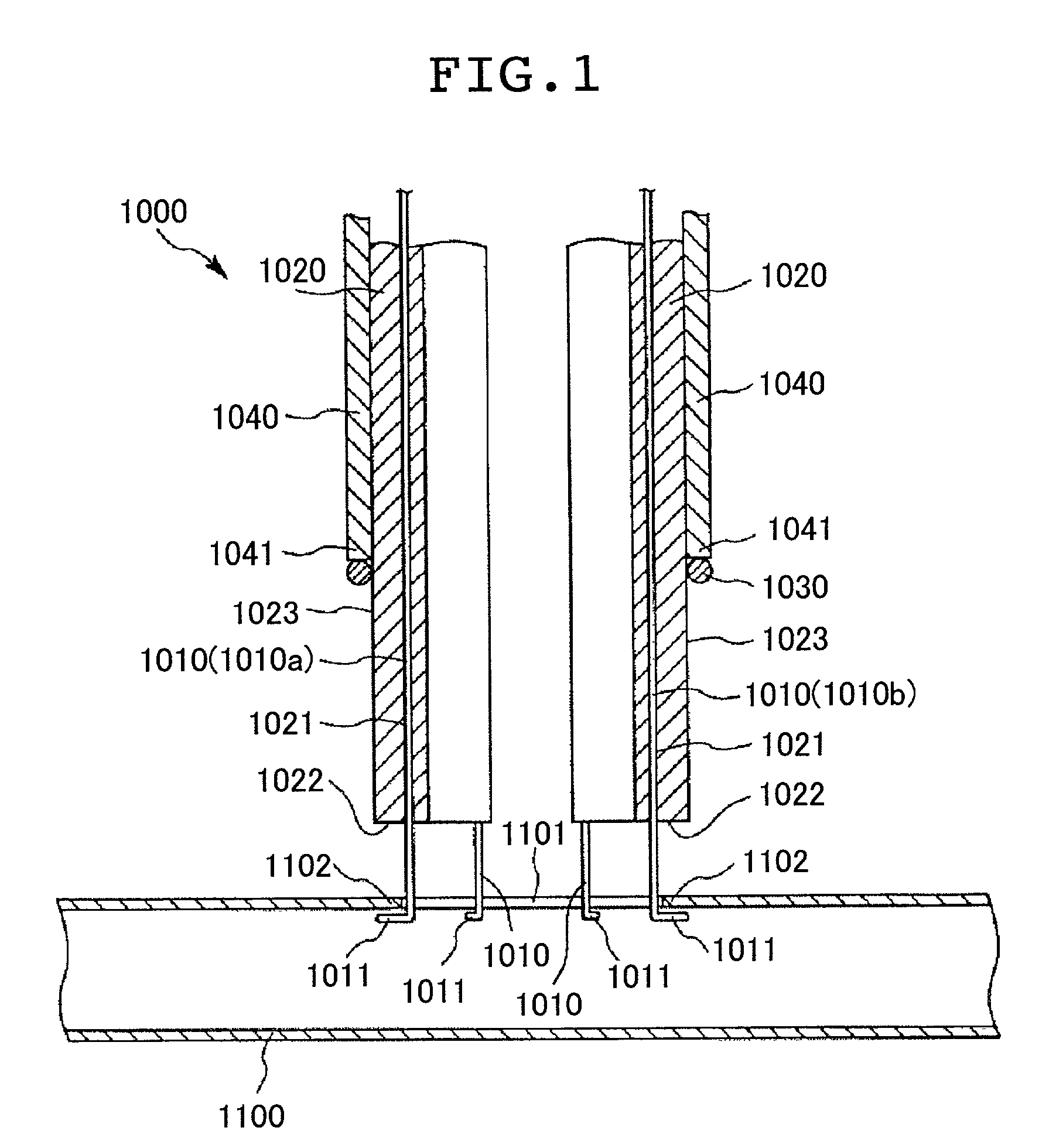
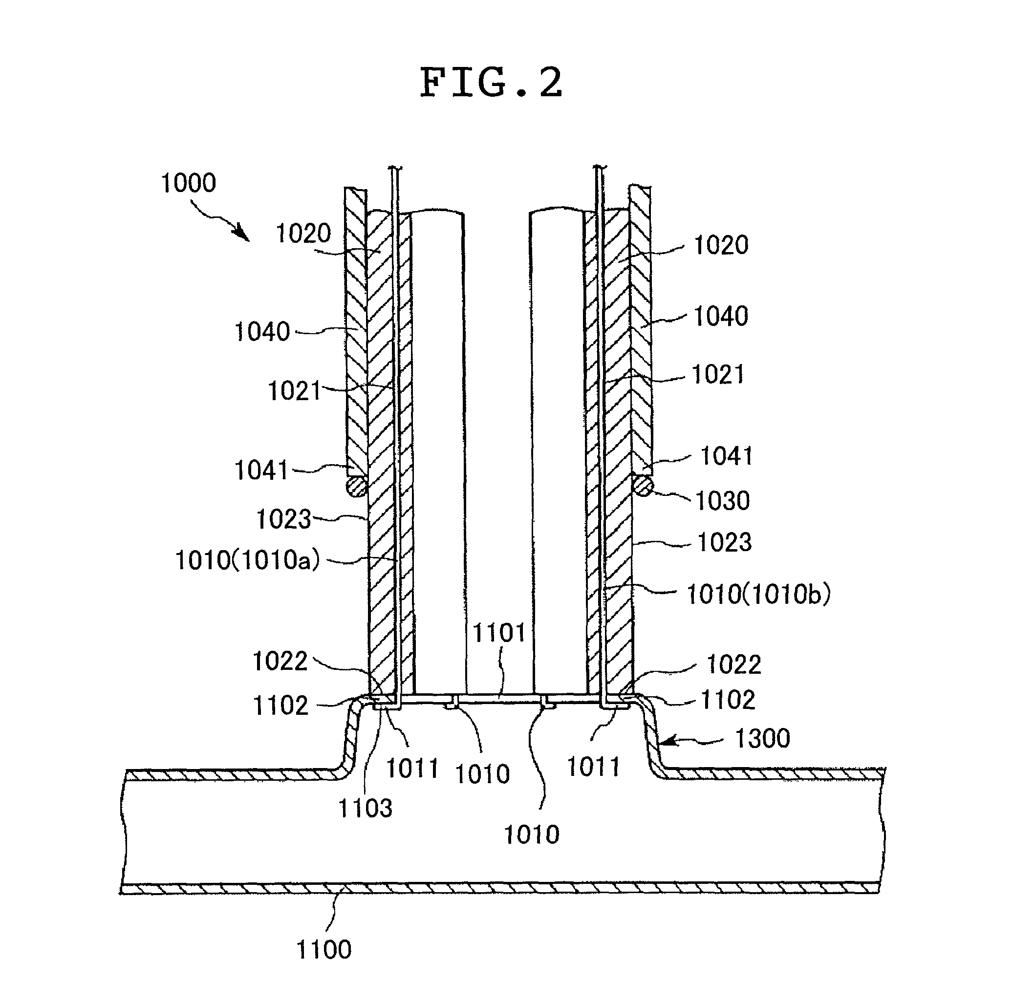
[0084] FIGS. 1 to 6 are each a longitudinal cross sectional view showing a blood vessel connecting instrument for use in an end-to-side blood vessel anastomosis method according to a first embodiment of the present invention. FIG. 7 is a perspective view showing a structure of a distal end portion of a blood vessel connecting instrument for use in an end-to-side blood vessel anastomosis method according to a first embodiment of the present invention. FIG. 8 is a plan view showing an engaging member for use in an end-to-side blood vessel anastomosis method according to the first embodiment of the present invention, illustrating a state in which the engaging member is attached to an opening of a blood vessel. FIG. 9 is partial side view showing structures of a blood vessel supporting member and a receiving member in the blood vessel connecting instrument for use in an end-to-side blood vessel anastomosis method according to the first embodiment of the present in...

second embodiment

[0126] Second Embodiment

[0127] FIG. 11 is a perspective view showing a blood vessel supporting instrument for use in the end-to-side blood vessel anastomosis method according to a second embodiment of the present invention. FIGS. 12 to 18 are schematic perspective views, respectively, illustrating in sequence the end-to-side blood vessel anastomosis method using this blood vessel supporting instrument according to a second embodiment of the present invention. In the following explanation, the upper side and lower side in FIG. 1 are referred to as "proximal end" and "distal end", respectively.

[0128] First, the blood vessel supporting instrument for use in the end-to-side blood vessel anastomosis method according to a second embodiment of the present invention will be illustrated in detail with reference to FIG. 11.

[0129] A blood vessel supporting instrument 2A shown in FIG. 11 comprises a pair of plate-like arm portions 21a and 21b and needle portions 22a and 22b provided on the dist...

third embodiment

[0155] Third Embodiment

[0156] FIG. 19 is a perspective view showing a blood vessel supporting instrument for use in the end-to-side blood vessel anastomosis method according to a third embodiment of the present invention. In the following explanation, the upper side and lower side in FIG. 19 are referred to as "proximal end" and "distal end", respectively.

[0157] The method of the third embodiment is the same as the method of the previous embodiments except that a blood vessel supporting instrument 2B shown in FIG. 19 is used.

[0158] Hereinafter, the method of the third embodiment will be illustrated in detail with reference to FIG. 19. The explanation will be centered on the differences from the methods of the previous embodiments and the explanation on the same or like matter will be omitted.

[0159] The blood vessel supporting instrument 2B shown in FIG. 19 is the same as the blood vessel supporting instrument 2A according to the second embodiment above except that an elastic member ...


PUM


Abstract

The method of end-to-side anastomosis of blood vessels by connecting a side portion of a first blood vessel to an end portion of a second blood vessel, comprises the steps of holding a first site on the side portion of the first blood vessel located in the vicinity of an peripheral portion of an opening formed on the side portion of the first blood vessel using a holder, and partially elevating the side portion of the first blood vessel; superimposing a second site on the side portion of the first blood vessel that is more distant from the peripheral portion of the opening formed on the side portion of the blood vessel than the first site is and the end of the second blood vessel and fixing them with a ring-shaped fixing member to each other; and detaching the holder from the first blood vessel when they are fixed by the fixing member or after they are fixed. The end-to-side blood vessel anastomosis method can readily open the dissected portion on the side of the blood vessel upon end-to-side blood vessel anastomosis and retain it in that state. In addition, no foreign matter is present within the blood vessel after completion of the anastomosis.

Description

[0001] 1. Field of the Invention[0002] The present invention relates to a method of anastomosis of blood vessels, more particularly to a method of an end-to-side anastomosis of an end portion of one blood vessel to a side portion of another blood vessel and instruments used for this anastomosis method. Also, the present invention relates to a method of connection of a medical device constituting an extracorporeal circulation circuit, such as a pump-oxygenator, a dialyser for blood or body fluid, at a side portion of a blood vessel.[0003] 2. Description of the Related Art[0004] In operations, an end-to-side anastomosis by connection of an end portion of a blood vessel with a side portion of another blood vessel to communicate the blood vessels with each other is sometimes carried out. For example, in coronary artery bypass graft (CABG) for the therapy of angina pectoris, cardiac infarction, arrythmia and so forth caused by insufficient circulation to the cardiac muscle due to the con...

Claims


Application Information

Patent Timeline
Patent Type & Authority Applications(United States)
IPC IPC(8): A61B17/11A61B17/32A61B19/00
CPCA61B17/11A61B17/320016A61B17/32053A61B2017/320052A61B2017/1107A61B2017/1135A61B19/26A61B90/50
Inventor KATO, YUKITOSHI
Owner TERUMO KK
Why Eureka
Try Eureka