Magnetically actuated micro-electro-mechanical apparatus and method of manufacture

a micro-electro-mechanical and magnetic actuator technology, applied in the direction of generators/motors, instruments, optical elements, etc., can solve the problems of coils requiring space, non-orthogonal actuation consumes greater power, and complicates the control of the devi

Inactive Publication Date: 2002-05-02
CORNING INC
View PDF11 Cites 108 Cited by
  • Summary
  • Abstract
  • Description
  • Claims
  • Application Information

AI Technical Summary

Problems solved by technology

Non-orthogonal actuation consumes greater power (or requires stronger magnetic fields) since the coil torques interfere with each other.
This also complicates control of the device.
In addition, the coils require space and reduce the area available for the mirror.
Smaller mirrors cannot intercept as much of the desired optical beam, causing higher insertion loss.
The relatively large magnets and frame make it difficult to have multiple mirrors of this type positioned close to each other in an array.
In addition

Method used


Image

  • Magnetically actuated micro-electro-mechanical apparatus and method of manufacture
  • Magnetically actuated micro-electro-mechanical apparatus and method of manufacture
  • Magnetically actuated micro-electro-mechanical apparatus and method of manufacture

Examples


Embodiment Construction

[0019] In accordance with one embodiment of the invention, an array of magnetically actuated MEMS mirror devices is provided having stationary magnets configured to provide strong magnetic fields in the plane of the mirrors without any magnets or magnet-system components in the plane of the mirrors.

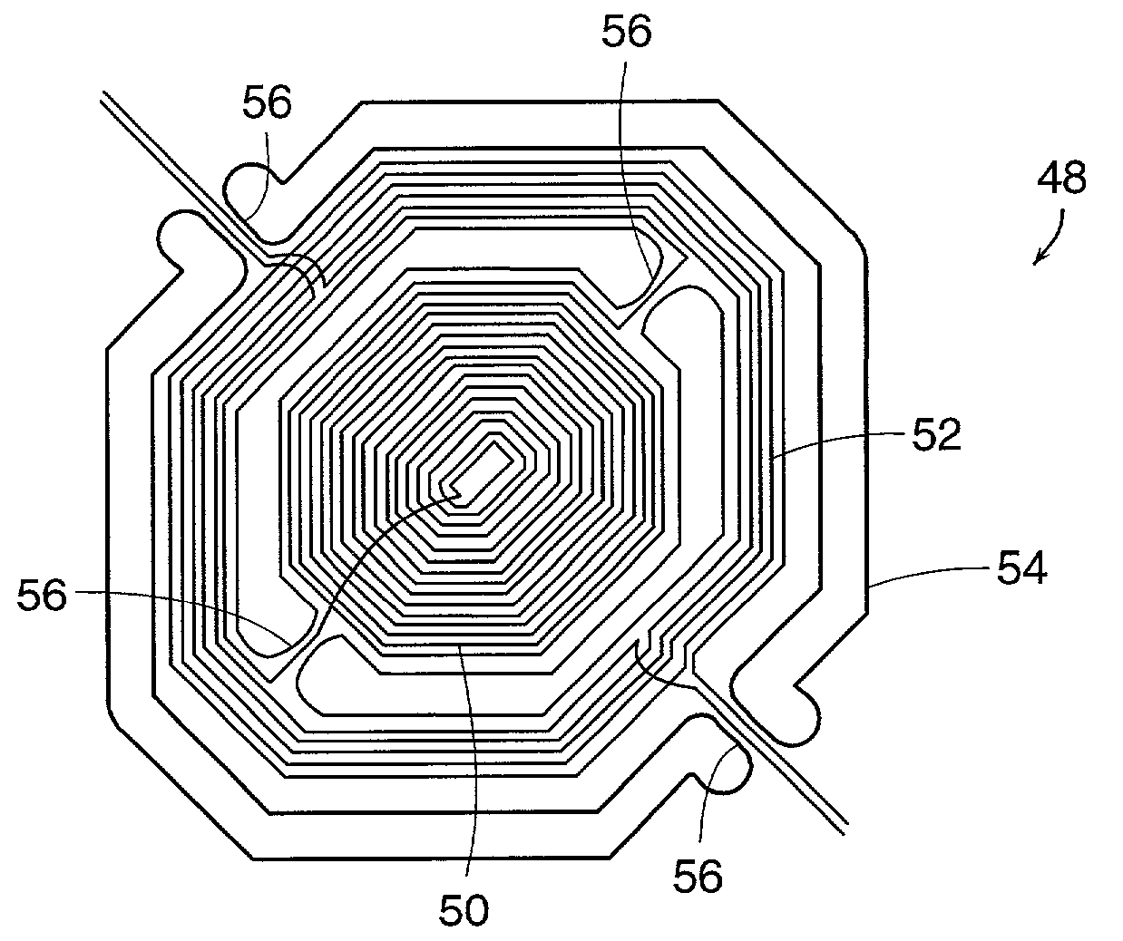
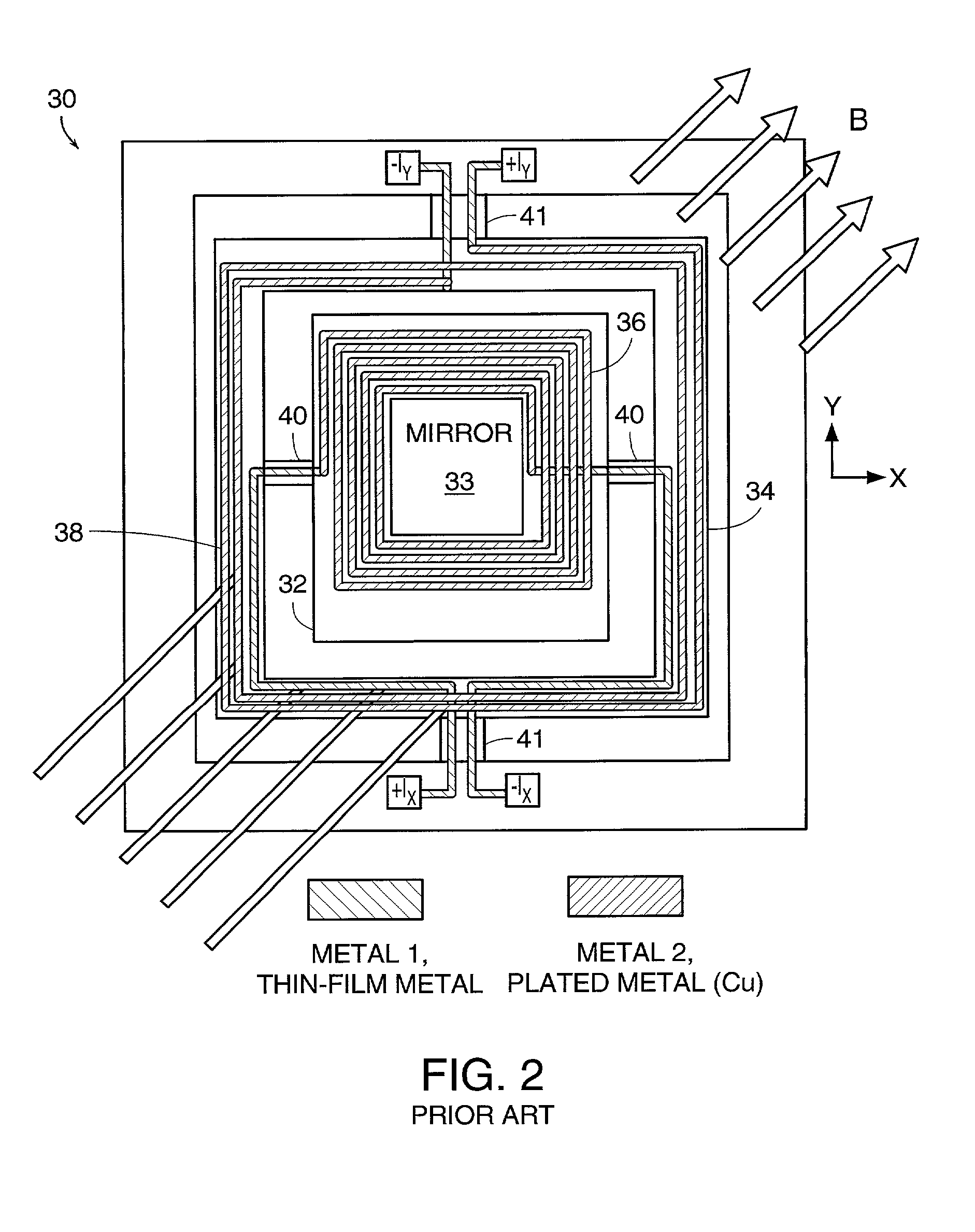
[0020] A magnetically actuated mirror device in accordance with another embodiment of the invention includes an improved actuation coil configuration that provides greater torque during mirror actuation.

[0021] In accordance with another embodiment of the invention, a mechanism is provided to detect the angular deflection of a moveable mirror.

[0022] In accordance with yet another embodiment of the invention, an improved process is provided for manufacturing MEMS mirror devices.

[0023] These and other features of various embodiments of the present invention will become readily apparent from the following detailed description wherein embodiments of the invention are shown and described by way...


PUM


Abstract

An array of magnetically actuated MEMS mirror devices is provided having stationary magnets configured to provide strong magnetic fields in the plane of the mirrors without any magnets or magnet-system components in the plane of the mirrors. Also, a magnetically actuated mirror device is provided that includes an improved actuation coil configuration that provides greater torque during mirror actuation. In addition, a mechanism is provided to detect the angular deflection of a moveable mirror. Also, an improved process is provided for manufacturing MEMS mirror devices.

Description

[0001] The present application is based on and claims priority from provisional patent application Ser. No. 60 / 276,815 filed on Mar. 16, 2001 and provisional patent application Ser. No. 60 / 228,332 filed on Aug. 27, 2000.[0002] 1. Field of the Invention[0003] The present invention relates generally to micro-electromechanical (MEMS) devices and, in particular, to arrayed magnetically actuated MEMS devices such as arrayed mirrors used in optical switches.[0004] 2. Description of Related Art[0005] FIG. 1 schematically illustrates an example of an optical cross-connect 12 of an optical switch. The cross-connect 12 includes an array of collimators or other beam-forming devices, represented by grid 14, and forms incoming optical communications signals into beams that impinge on an array of selectively moveable reflectors or mirrors represented by grid 16. Each beam from grid 14 has its own corresponding moveable mirror on grid 16.[0006] The moveable mirrors of grid 16 are controllably posi...

Claims


Application Information

Patent Timeline
IPC IPC(8): B81B3/00G02B26/08
CPCB81B3/0062B81B7/04B81B2201/045G02B26/085B81C2203/0109B81C2203/035G02B26/0841B81B2207/015
Inventor BERNSTEIN, JONATHANTAYLOR, WILLIAM P.KIRKOS, GREGORY A.WAELTI, MARC
Owner CORNING INC
Why Eureka
Try Eureka