Temperature control of electronic devices using power following feedback

a technology of electronic devices and feedback, applied in the field of temperature control, can solve the problems of high volume chip manufacturing, difficult to maintain chip temperature near a constant set point, and significant temperature difference to tes

Inactive Publication Date: 2002-05-02
SCHLUMBERGER AUTOMATED TEST EQUIP +1
View PDF0 Cites 51 Cited by
  • Summary
  • Abstract
  • Description
  • Claims
  • Application Information

AI Technical Summary

Problems solved by technology

But if the instantaneous power dissipation of the chip varies up and down in a wide range while operating or testing, then maintaining the chip temperature near a constant set point is very difficult.
There are several problems with the use of temperature sensing devices.
At some level of power dissipation, this temperature difference will be significant to the test result.
The use of temperature sensors integrated into the chip itself addresses this problem, but

Method used


Image

  • Temperature control of electronic devices using power following feedback
  • Temperature control of electronic devices using power following feedback
  • Temperature control of electronic devices using power following feedback

Examples


Embodiment Construction

[0038] The above-noted and other aspects of the present invention will become more apparent from a description of an embodiment, when read in conjunction with the accompanying drawings. The drawings illustrate an embodiment of the invention. In the drawings, the same members have the same reference numerals.

[0039] Pending patent application U.S.S.N. 08 / 734,212 to Pelissier, assigned to the present assignee, is hereby incorporated as fully set forth herein. Co-pending provisional patent application U.S.S.N. 60 / 092,715to Jones et al. (attorney docket number 42811-106), also assigned to the present assignee, filed on Jul. 14, 1998, is also hereby incorporated as if fully set forth herein.

[0040] 1. Central Principles

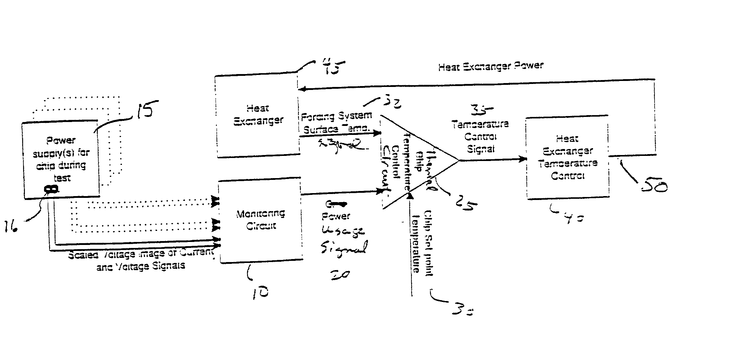
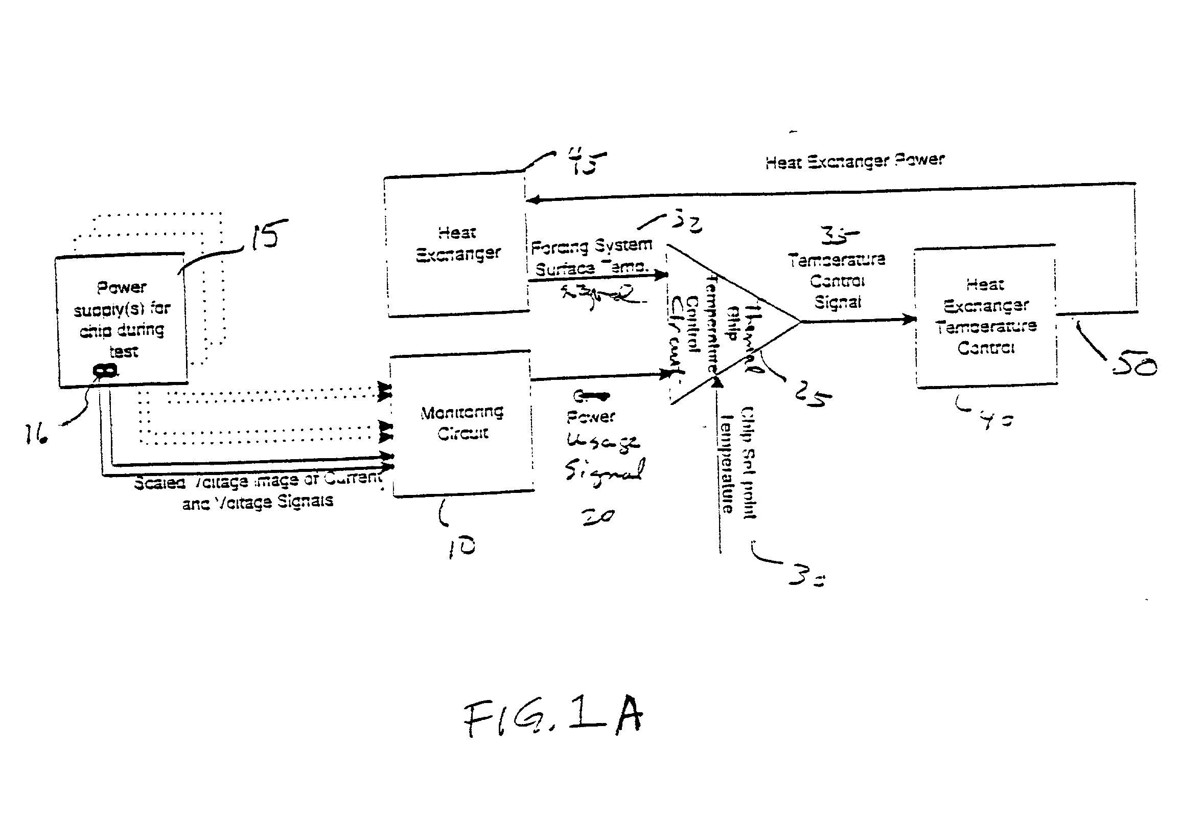
[0041] When a device is tested, the tests need to be run at a specified temperature, known as a set point. The device, which is also called the device under test ("DUT"), is typically tested at several different set points and the performance at each set point is noted. The ...


PUM


Abstract

A method for controlling a device temperature measures a parameter related to device power consumption and utilizes the parameter to control the device temperature. This can be achieved with a system including a heat exchanger, a power monitor, and a circuit which controls the temperature setting of the heat exchanger. The circuit uses as inputs the power level, heat exchanger temperature, and set point. The system thus eliminates the need for temperature sensing devices in or connected to a chip, responds to the temperature of the device and not the package, can be used for high volume chip manufacturing, does not require significant surface area of a device for temperature sensing, and eliminates the need for chip power profiles. Significantly, the system allows a set point to be maintained with minimal overshoot or undershoot.

Description

[0001] This application claims the priority of previously filed provisional application number 60 / 092,720, filed on Jul. 14, 1998, which is hereby incorporated as if fully set forth herein.[0002] 1. Field of the Invention[0003] This invention relates in general to the field of temperature control and more particularly to an improved apparatus and method of providing temperature control to electronic devices using power following feedback.[0004] 2. Description of Related Art[0005] The present invention relates to temperature control systems which maintain the temperature of an electronic device at or near a constant set point temperature while the device is being operated or tested. Two examples of electronic devices which are best operated at a constant or near constant temperature are packaged integrated chips and bare chips which are unpackaged. Maintaining the chip temperature near a constant set point is not difficult if the power dissipation of the chip is constant or varies in...

Claims


Application Information

Patent Timeline
IPC IPC(8): G01R31/28G05D23/20G05D23/24H01L23/34
CPCG01R31/287G01R31/2874G05D23/20G05D23/2401H01L2924/0002H01L23/34H01L2924/00
Inventor JONES, THOMAS P.TURNER, JONATHAN E.MALINOSKI, MARK F.
Owner SCHLUMBERGER AUTOMATED TEST EQUIP
Why Eureka
Try Eureka