Floor covering

a technology for floor coverings and walls, applied in the field of floor coverings, can solve problems such as difficulty in carrying out said rotation

Inactive Publication Date: 2002-05-16
FLOORING IND LTD
View PDF4 Cites 206 Cited by
  • Summary
  • Abstract
  • Description
  • Claims
  • Application Information

AI Technical Summary

Problems solved by technology

A disadvantage of the known embodiments of the above-mentioned plates consists in that it is often difficult to carry out sai...

Method used


Image

  • Floor covering
  • Floor covering
  • Floor covering

Examples


Embodiment Construction

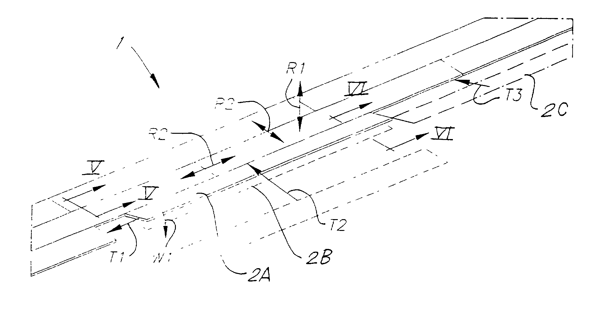
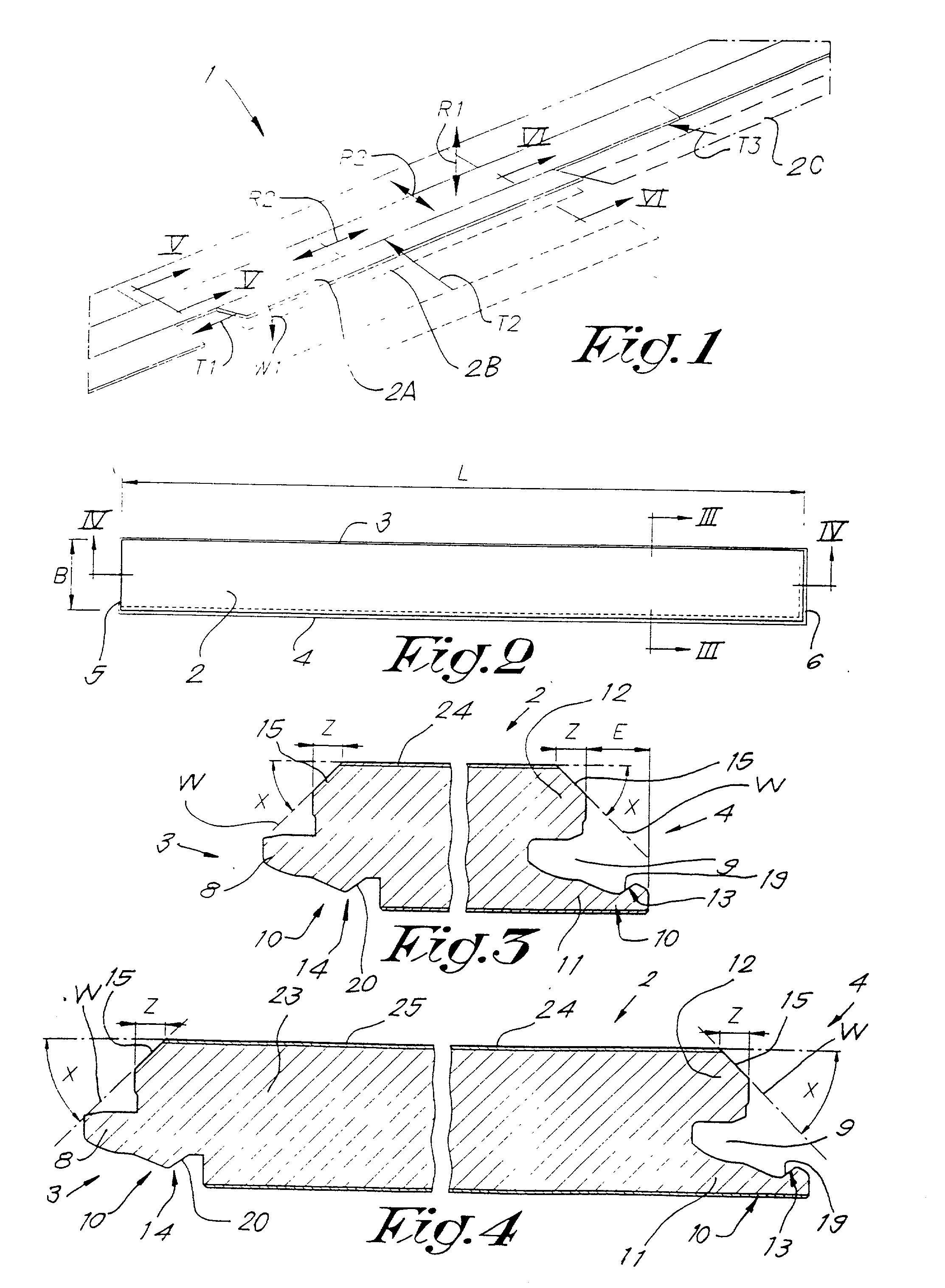
[0058] As represented in FIGS. 1 and 2, the invention concerns a floor covering 1 as well as hard panels 2 from which such a floor covering 1 is built up.

[0059] According to a first aspect of the invention, a floor covering 1 is concerned, consisting of hard panels 2, whereby these panels 2 are provided at least on two opposite edges 3-4, and preferably, as represented in the FIGS. 2 to 8, on both pairs of edges 3-4, 5-6 respectively, with coupling means or elements 7 made in one piece out of the material of the panels 2, so that several of such panels 2 can be mutually coupled to one another, whereby these coupling means 7 provide for an interlocking in a direction R1 perpendicular to the plane of the floor covering 1, as well as in, a direction R2 perpendicular to the edges 3-4 or 5-6 concerned and parallel to the plane of the floor covering 1, and whereby these coupling means 7 are made such that the panels 2 can be assembled and / or disassembled at least along the above-mentioned...


PUM


Abstract

A floor covering of hard panels (2) having at least on two opposite edges (3-4; 5-6), coupling elements (7) made in one piece with the panels (2), so that several of such panels (2) can be mutually coupled, whereby these coupling elements (7) provide for an interlocking in a direction (R1) perpendicular to the plane of the floor covering (1), as well as in a direction (R2) perpendicular to the edges (3-4; 5-6) and parallel to the plane of the floor covering (1), and whereby these coupling elements (7) are made such that the panels (2) can be rotated into and/or out of one another at least along the above-mentioned edges (3-4; 5-6). The panels (2) are provided, at least on the above-mentioned edges (3-4; 5-6), near the top side, with a part from which has been removed an amount of material such as by a level.

Description

[0001] 1. Field of the Invention[0002] The present invention concerns a floor covering, in particular of the type consisting of hard panels.[0003] 2. Related Art[0004] In a particular, yet not restrictive manner, it concerns a floor covering formed of laminate panels, also called laminate parquet.[0005] It is known that such laminate panels can be made of different layers. Usually, the panels are formed of boards on the basis of wood, such as chipboard or fibreboard, in particular MDF or HDF, upon which one or several layers, including a decorative layer, are provided at least on the top side. The decorative layer may be a printed paper layer, but in certain embodiments it may just as well be a layer of wood, in particular veneer. Such panels can also be made of other materials, for example merely synthetic material, or of a base plate on the basis wood, such as chipboard, MDF or HDF and the like, upon which is provided, instead of a printed paper layer or veneer, another material s...

Claims


Application Information

Patent Timeline
IPC IPC(8): B44C1/24E04F15/02B44C5/04B44F9/02E04F15/04
CPCB44C1/24Y10T156/1039B44C5/043B44C5/0446B44C5/0453B44F9/02E04F15/02E04F15/02033E04F15/04E04F15/181E04F2201/0115E04F2201/0153E04F2290/043Y10T156/1044Y10T428/24802Y10T428/24438B44C5/04
Inventor THIERS, BERNARD PAUL JOSEPH
Owner FLOORING IND LTD
Why Eureka
Try Eureka