Solid-appearing fence system

a fence system and solid-looking technology, applied in fencing, building types, constructions, etc., can solve the problems of inability to build fences made of soil-based materials, prohibitive labor and soil-based materials, and the cost and labor requirements for constructing the solid-looking fence system are substantially lower than the cost and labor requirements for typical fences, so as to facilitate the horizontal engagement of members, easy to be lifted, and easy to construct

Inactive Publication Date: 2002-05-16
HAZAN AVSHALOM
View PDF0 Cites 10 Cited by
  • Summary
  • Abstract
  • Description
  • Claims
  • Application Information

AI Technical Summary

Benefits of technology

[0012] Each column and wall member includes an interior cage covered with a plurality of thin panels. The interior cage of each column includes a plurality of longitudinally aligned legs and a plurality of transversely aligned cross-members spaced apart and connected together to form a lightweight, supporting skeleton framework square or rectangular in cross-section. When panels are attached to the interior cage, an unobstructed, longitudinally aligned space is formed inside the column in which wiring, electrical conduit, plumbing pipes, light fixtures, mail boxes, etc. may be inserted. During assembly, the distal ends of the legs are uncovered. Because the column is lightweight, it may be easily lifted and forced downward into the soil, thereby embedded the distal ends of the legs directly into the soil. An optional small layer of concrete may be poured into the column covering the soil and the lower section of the cage to add a counterweight.
[0014] The thin panels are made of lightweight, weather resistant material are easily attached to the sides of the interior cages visible to an outside viewer. In one embodiment, the panels are made of thin slabs of concrete commonly known as concrete board with finished or unfinished outer surfaces. In another embodiment, an outer layer of brick, rock or stucco is applied over the outer surface of the concrete board. In a third embodiment, the panels are made of foam with an outer surface having three-dimensional features and texture that simulate concrete, brick, rock or stucco and a full length, inner sheet of aluminum. In a fourth embodiment, the panels are made of lightweight foam or aerated concrete with a plurality of integrally attached clips extended from the inside surface. The clips are sufficiently spaced apart and designed to easily engage the horizontal members on either the column or wall member by slightly lifting the panel and allowing it to fall so that the clips engage the horizontal members.
[0015] The columns and wall members are designed to be easily constructed on-site or offsite. When fully constructed, the columns may be easily lifted and moved to its desired position by one or two individuals. The columns are designed to be easily attached to the soil by forcing the distal ends of the legs downward into the soil. Depending on the amount of wind or lateral forces to be exerted to the column, an optional layer of concrete may then be poured into the bottom end of the column covering the exposed soil and lower end of the interior cage to be provided weight. If the column needs to be moved, the layer of concrete can be easily chipped away so that it may be easily lifted by hand while fully assembled to its new location.
[0016] Because each the column and wall members are hollow electrical boxes, light fixtures, electrical and plumbing conduit, and mail boxes may be easily installed. Optional removable caps may also be used on the columns and wall members that provide greater access to their center spaces. Also, because the panels are made of thin concrete they are very durable, weather resistant, capable of being painted or covered with other layers (i.e brick, rock, stucco, paint), easily cut-to-size, and easily replaced or repaired with concrete patching material, retrofit construction is possible. Optional light fixtures and moldings may be attached to the top, sides and bottom surfaces of the columns and wall members to provide a more finished, attractive appearance.

Problems solved by technology

Unfortunately, with current fence or wall designs using these materials, the costs for labor and the soil-based materials is prohibiting.
While, many "do-it-yourself" homeowners build wood fences, most homeowners will not build fences made of soil-based materials because they do not possess the required masonry skills.
The cost and labor requirements for constructing the the solid fence system, however, are substantially lower than the costs and labor requirements for typical fences made entirely of these materials.

Method used


Image

  • Solid-appearing fence system
  • Solid-appearing fence system
  • Solid-appearing fence system

Examples


first embodiment

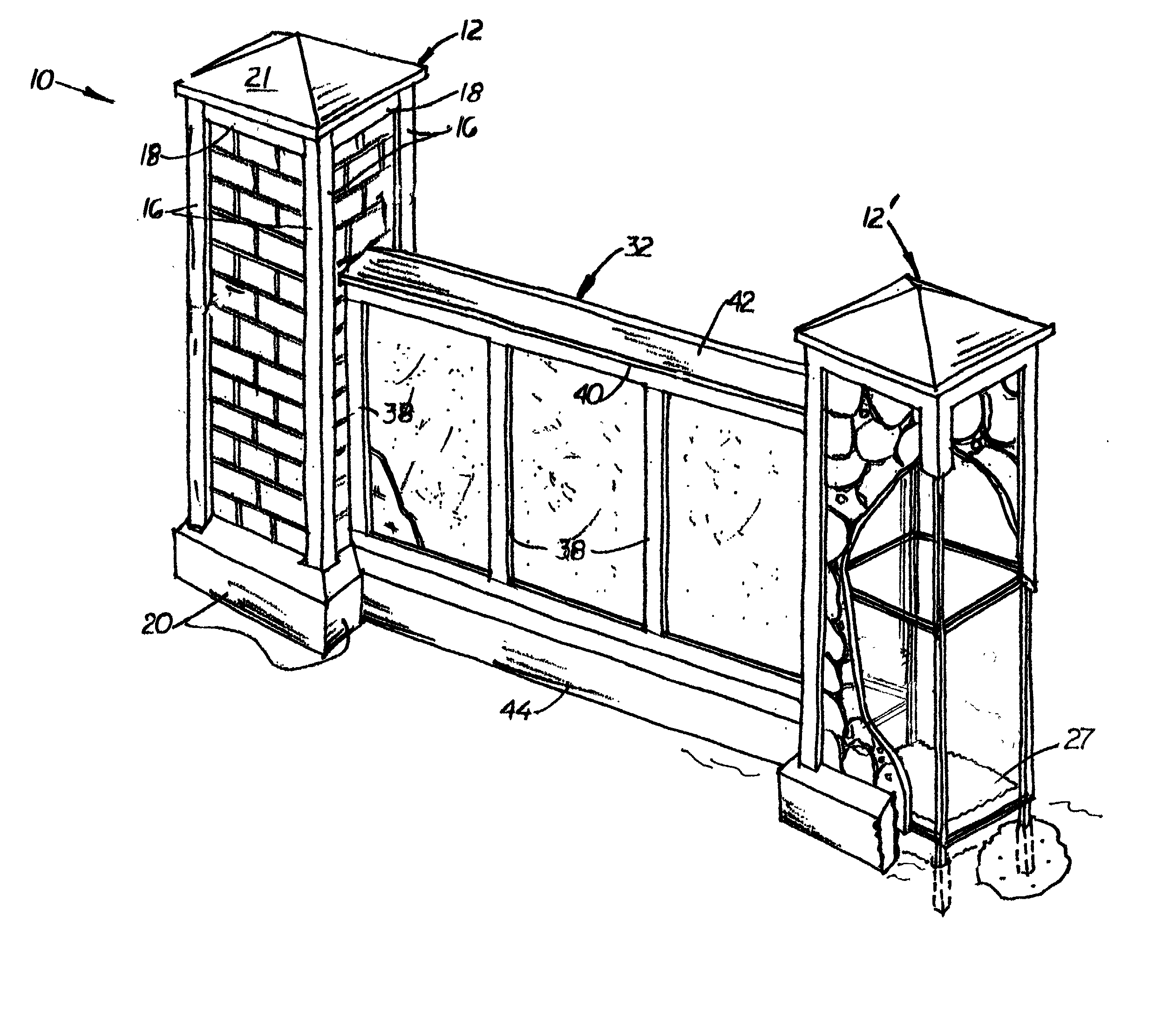
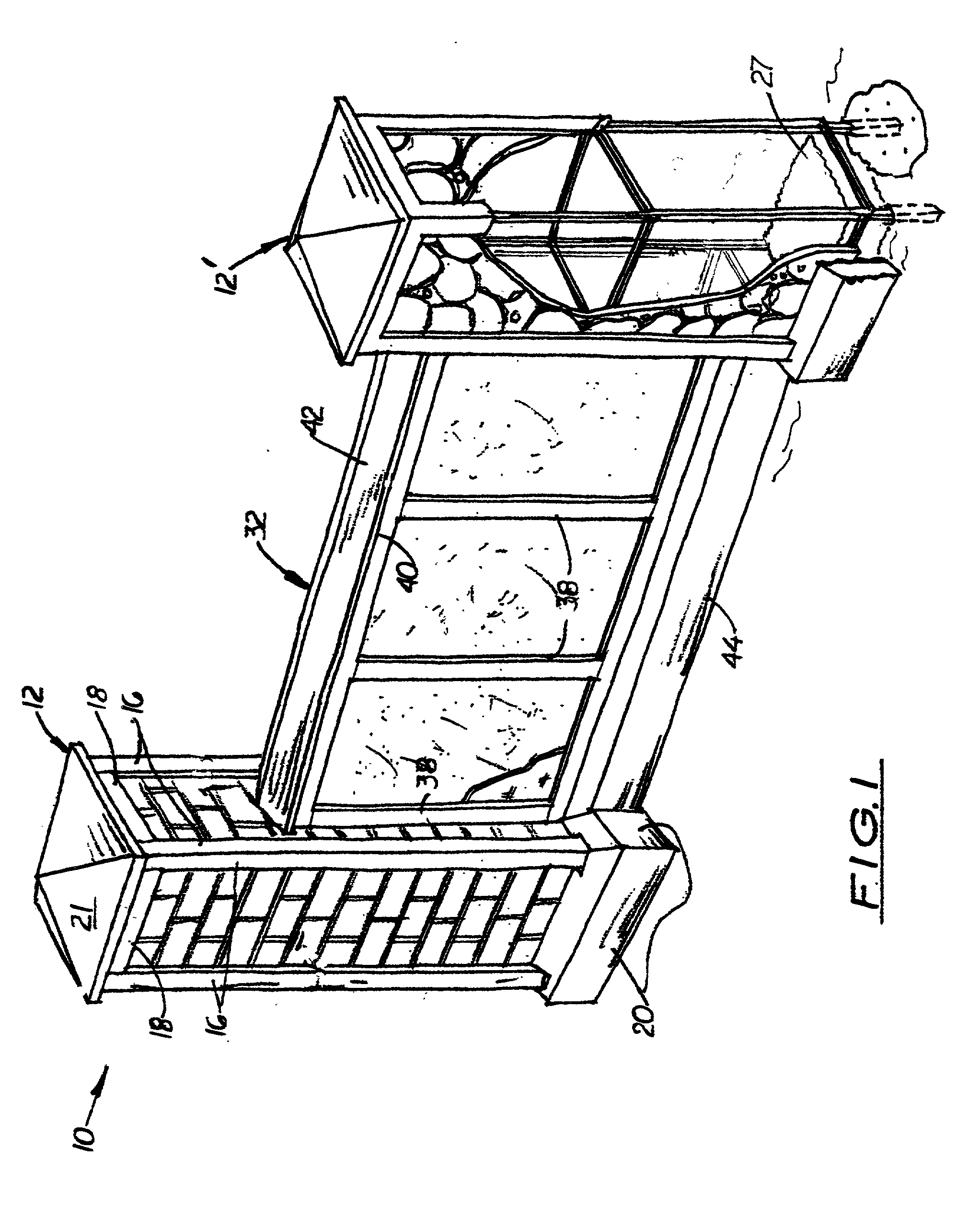
[0032] In the first embodiment, panels 29, 60 are made of thin concrete with are exposed outer surfaces, thereby making the columns 12 and wall members 32 appear to be a solid structures made of concrete. In other embodiments, an optional layer of brick 65, rock 67, or stucco 69 may be constructed over the outer surfaces of panels 29, 60, as shown in FIGS. 3-4. Removable caps 21 or 42 or lighting fixture (not shown) may be attached to the top of each column 12, or wall member 32, respectively, to create fully enclosed structures. Wood moldings 16, 18, 20, and 38, 40, 44 may also be attached to the sides of the columns 12 and wall members 32, respectively, to provide a more finished, attractive appearance.

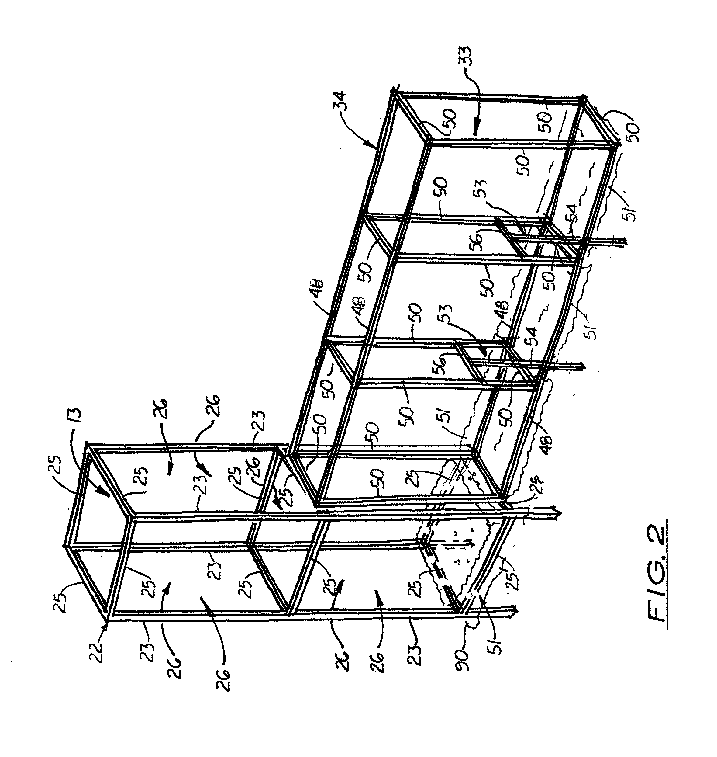
[0033] The column's interior cage 22 includes four longitudinal legs 23 and a plurality of transversely aligned cross-members 25. The longitudinal legs 23 and cross-members form a skeleton framework 24, square or rectangular in cross-section with an unobstructed longitudinally align...

third embodiment

[0043] In FIGS. 11 and 12, a panel 84 is shown which includes a plurality of clips 87 that extend inward from the inside surface 85 to engage a vertical or horizontal member on the column or wall. The clips 87 are spaced apart approximately the same distance (12 to 24 inches) as the longitudinally legs and members, and cross-members. In the preferred embodiment, the clips 87 are leg extensions formed on a wire mesh 88 material commonly used to construct concrete slabs. During assembly, the panel 84 is lifted and positioned in a vertical orientation adjacent to the surface of the column 12 or wall member 32 to be covered. The panel 84 is then lifted and pressed inward so that some or all of the clips 87 may engage the adjacent member. The clips 87 are L-shaped so that gravitational forces hold the panel in place on the horizontal member. Suitable connectors similar to the connectors used with panels 29, 60, 72, may then be used to more securely attach the panels 87 to the column 12 o...


PUM


Abstract

A fencing system that has the appearance of having solid columns and panels made of concrete, brick, rock, or stucco, yet is substantially less expensive to construct. The system includes a plurality of hollow columns and hollow wall members, both with interior cages covered with thin, relatively inexpensive panels. The panels may be easily attached to the exposed surfaces of the interior cages. In one embodiment, the panels are made of concrete, which may be exposed or are sufficiently durable to be covered with soil-based materials, such as brick, rock, or stucco thereby creating the appearance that the entire fence is made of these materials. In another embodiment, the panels are made of lightweight foam with an aluminum sheet packing. The interior cage of the column includes a plurality of vertical legs, which during construction, are embedded into a concrete footing. The interior cage of the wall member is disposed and connected in an end-to-end manner to the interior cages of the two adjacent columns. A decorative cap or lighting fixture may be attached to the top of each column, and moldings may be attached to the sides and bottom edges to provide a more finished, attractive appearance. Also, decorative molding or bars may be added to the panels.

Description

[0001] This is a continuation-in-part application based upon utility patent application (Ser. No. 09 / 499,935) filed on Feb. 8, 2000, which was based on provisional patent application (Ser. No. 60 / 153,311) filed on Sep. 10, 1999.[0002] 1. Field of the Invention[0003] This invention pertains to wall or fence systems and more particularly, to wall or fence systems that have an overall appearance of being made of durable, weather-resistant, and soil-based material, such as rock, concrete, brick, or stucco.[0004] 2. Description of the Related Art[0005] It is common to construct fences around residences for privacy and security reasons. Typically, such fences are set along a boundary line of a residence, and are comprised of a plurality of vertically aligned, spaced-apart, wooden posts set in holes partially filled with concrete. Two horizontally aligned, wooden rails are disposed between the posts, and a plurality of vertically aligned boards is attached between the two rails to form the...

Claims


Application Information

Patent Timeline
Patent Type & Authority Applications(United States)
IPC IPC(8): E04H17/16
CPCE04H17/16
Inventor HAZAN, AVSHALOM
Owner HAZAN AVSHALOM
Why Eureka
Try Eureka