Acoustic inspection of one-piece bladed wheels

a one-piece bladed wheel and acoustic inspection technology, which is applied in the direction of instruments, heat measurement, specific gravity measurement, etc., can solve the problems of resonance not being able to destroy the wheel on which the blades are mounted, and the wheel being completely destroyed, so as to avoid the effect of potential destruction of the wheel

Inactive Publication Date: 2002-05-23
SN DETUDE & DE CONSTR DE MOTEURS DAVIATION S N E C M A
View PDF0 Cites 40 Cited by
  • Summary
  • Abstract
  • Description
  • Claims
  • Application Information

AI Technical Summary

Benefits of technology

[0005] An object of the present invention is to provide a method-and a corresponding apparatus for acoustic inspection of one-piece bladed wheels that enable this risk of resonance to be identified, in order to avoid potential destruction of the wheel. Another object of the invention is to propose an inspection method which is particularly fast and which can be implemented in real time. Another object of the invention is to propose an inspection method which can form an integral portion of the machining process. Yet another object of the invention is to propose a method which also makes it possible to inspect the quality of the machining. A further object of the invention is to propose a method which can also determine the types of defect that affect any blades found to be defective.
[0007] With this particular method, it is possible for a wheel that is not compliant to be identified very quickly and without error. Furthermore, the method can be integrated without difficulty in a conventional machining process.

Problems solved by technology

One consequence of individually mounting blades in that way is to cause vibratory phenomena to be damped, thereby making it impossible, in practice, for resonance to destroy a wheel on which blades are mounted.
Unfortunately, modern means for automatic machining enable very great precision and very great repeatability to be achieved in the manufacture of blades, and an unexpected consequence of an almost perfect shape being made is to provoke very large resonant vibratory phenomena which can, under extreme circumstances, lead to the wheel being completely destroyed.

Method used


Image

  • Acoustic inspection of one-piece bladed wheels
  • Acoustic inspection of one-piece bladed wheels
  • Acoustic inspection of one-piece bladed wheels

Examples


Embodiment Construction

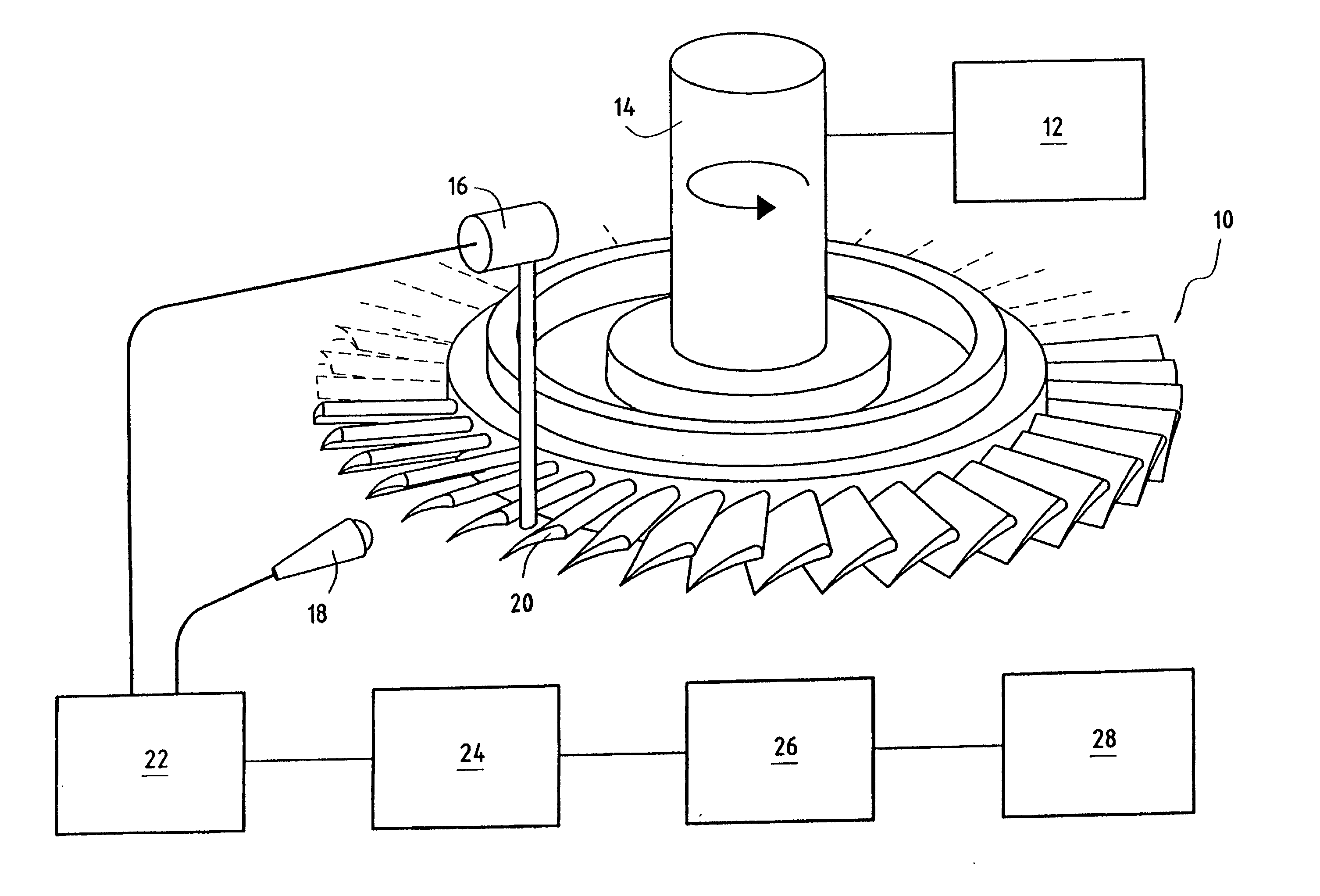
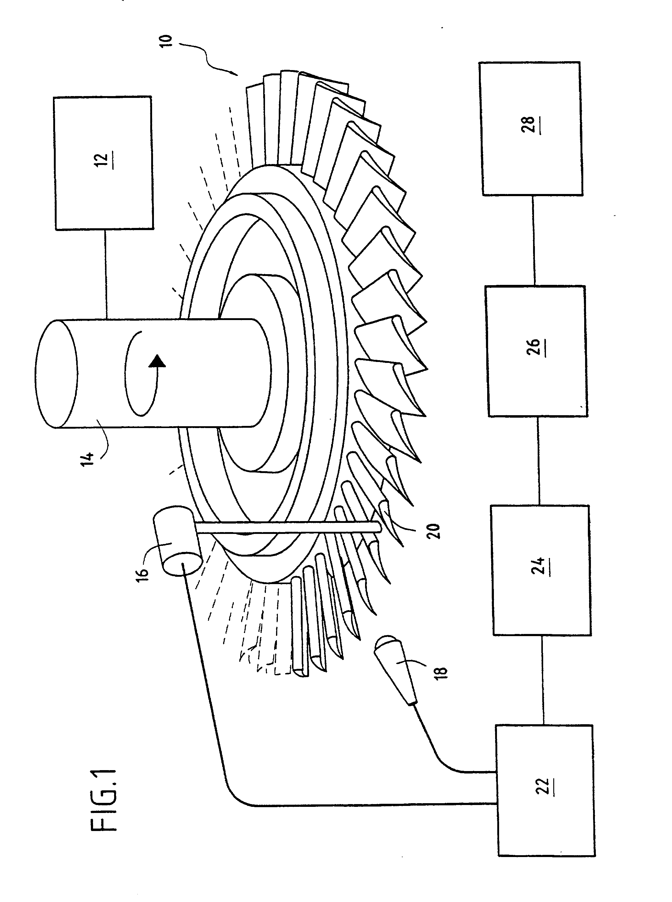
[0013] The apparatus of the invention for acoustically inspecting one-piece bladed wheels is shown very diagrammatically in FIG. 1. It comprises means for rotating a wheel 10, which means are constituted, for example, by an electric motor 12 driving a hub 14 on which the wheel for inspection is placed (an indexing system, not shown, is also provided in order to identify each of the blades of the wheel); mechanical excitation means 16 are placed above a blade 20 of the wheel, by way of example these means can be constituted by a percussion device or by releasing a hammer (e.g. a metal strip or finger); acoustic receiver means 18, e.g. constituted by a microphone, are placed in the vicinity of the excited blade; and processor means 22-28 are connected to control the mechanical excitation means 16 and also to process the acoustic signals picked up from the terminals of the acoustic receiver means 18. Conventionally, for each blade of the wheel, processing of the acoustic signals is syn...


PUM

PropertyMeasurementUnit
frequencyaaaaaaaaaa
frequencyaaaaaaaaaa
thicknessaaaaaaaaaa

Abstract

These objects are achieved by a method of acoustically inspecting a one-piece bladed wheel in which the wheel is driven in rotation; each blade of the wheel is subjected to mechanical excitation; its acoustic response is picked up and a corresponding electrical signal is generated; its frequency response is determined by computing a FFT; the electrical signal and the associated frequency response are stored; the characteristic frequencies of each blade of the wheel are identified; and a wheel is rejected or accepted depending on whether or not the frequency distribution obtained in this way matches a predetermined set of forbidden frequency distributions. Advantageously, an additional step is provided in which the defects of a blade are determined by comparing its frequency response with predetermined frequency responses that are characteristic of various types of defect.

Description

[0001] The present invention relates to the field of inspecting the machining of mechanical parts, and more particularly it relates to frequency inspection of one-piece bladed wheels by vibro-acoustic signature.PRIOR ART[0002] Until recently, the rotary portion or "rotor" of the compressor in a turbojet or a turbo-thruster (referred to below as a "turbomachine"), has been built up by assembling together a plurality of wheels in the form of disks or rings, with each wheel having blades, also known as "vanes", individually attached thereto. One consequence of individually mounting blades in that way is to cause vibratory phenomena to be damped, thereby making it impossible, in practice, for resonance to destroy a wheel on which blades are mounted.[0003] Nowadays, compressor wheels, and also industrial fan wheels, are being made more and more frequently as single pieces, with the blades being integral with the wheel disk or support ring. That type of structure serves to minimize the si...

Claims


Application Information

Patent Timeline
Patent Type & Authority Applications(United States)
IPC IPC(8): G01M7/00G01M15/14G01M99/00G01N29/04G01N29/44G01N29/46
CPCG01N29/045G01N29/4445G01N29/46G01N2291/2693G01N2291/101G01N2291/2638G01N2291/014
Inventor NAUDET, JACKYMARY, JEAN-LUCCOLLOT, ANDREBERTHILLIER, MARC
Owner SN DETUDE & DE CONSTR DE MOTEURS DAVIATION S N E C M A
Why Eureka
Try Eureka