Transfer of data in a telecommunications system

a technology of telecommunications system and data transfer, applied in data switching networks, high-level techniques, wireless commuication services, etc., can solve the problems of not being cost-effective to provide such processing circuitry, not being particularly efficient in handling other types of data, and significant processing circuitry required to decod

Active Publication Date: 2002-05-23
WI LAN INC
View PDF13 Cites 19 Cited by
  • Summary
  • Abstract
  • Description
  • Claims
  • Application Information

AI Technical Summary

Benefits of technology

[0011] In accordance with the present invention, a transmitter is provided within the central terminal for sending a data message destined for a particular subscriber terminal as a number of data blocks. A frame generator is then provided to generate a number of frames to represent each data block, each frame having a header portion and a data portion. In accordance with the present invention, the header portion is transmitted in a fixed format chosen to facilitate reception of the header portion by each subscriber terminal, and is arranged to include a number of control fields for providing information about the data portion. The choice of such a fixed format enables each subscriber terminal to receive the header portion, and hence in preferred embodiments the header portion can include information to enable each subscriber terminal to determine whether the corresponding data portion is destined for that subscriber terminal or not. This provides a particularly efficient technique for notifying subscriber terminals whether a data portion is destined for them, without the need for any subscriber terminal to begin processing the data portion itself in order to determine that information. Any subscriber terminals to which the data portion is not destined can merely ignore the data portion provided in that frame, thereby leaving the data portion to be processed by the subscriber terminal(s) to which that data portion is destined.
[0026] Accordingly, in preferred embodiments, the second number of processors are less than the first number of channel monitors, whereby at any point in time the header portions of the frames on each of the communication channels can be read, but only the second number of data portions can be processed by a particular subscriber terminal. By this approach, even though any particular subscriber terminal can only decode up to the second number of data portions at any one time, the central terminal has complete flexibility as to which communication channel data portions destined for that subscriber terminal are transmitted in, thus enabling the central terminal to make efficient use of the available resources of the transmission medium. In certain embodiments, some of the communication channels may exhibit better signal-to-noise ratios than other communication channels, and accordingly this flexibility can be used to make use of the communication channels that facilitate the use of the more efficient format.

Problems solved by technology

However, unlike voice data which is delay sensitive and thus requires continuous operation and relatively constant bit rates, other types of data (e.g. Internet protocol (IP) data) are often bursty, and typically are not delay sensitive, and accordingly the transport mechanisms provided for handling voice data are often not particularly efficient at handling transfer of such other types of data.
However, since the data portions are transmitted in a variable format, and are typically channel coded, significant processing circuitry is required to decode the data portions, and it will generally not be cost effective to provide such processing circuitry for each communication channel, since in most implementations the per subscriber data rate will be only a fraction of the transmission medium data rate.

Method used


Image

  • Transfer of data in a telecommunications system
  • Transfer of data in a telecommunications system
  • Transfer of data in a telecommunications system

Examples


Embodiment Construction

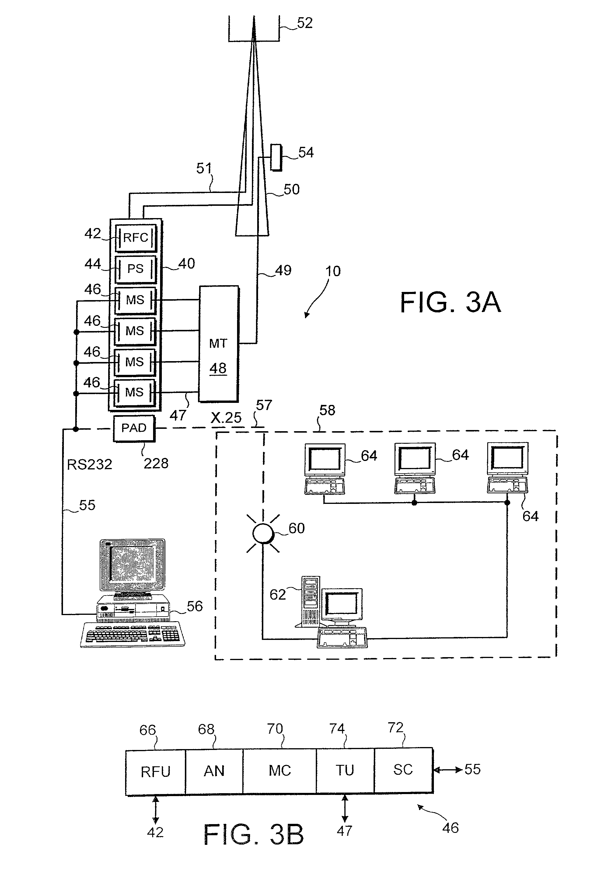
[0051] For the purposes of describing a preferred embodiment of the present invention, an implementation in a wireless telecommunications system will be considered. Before describing the preferred embodiment, an example of such a wireless telecommunications system in which the present invention may be employed will first be discussed with reference to FIGS. 1 to 3.

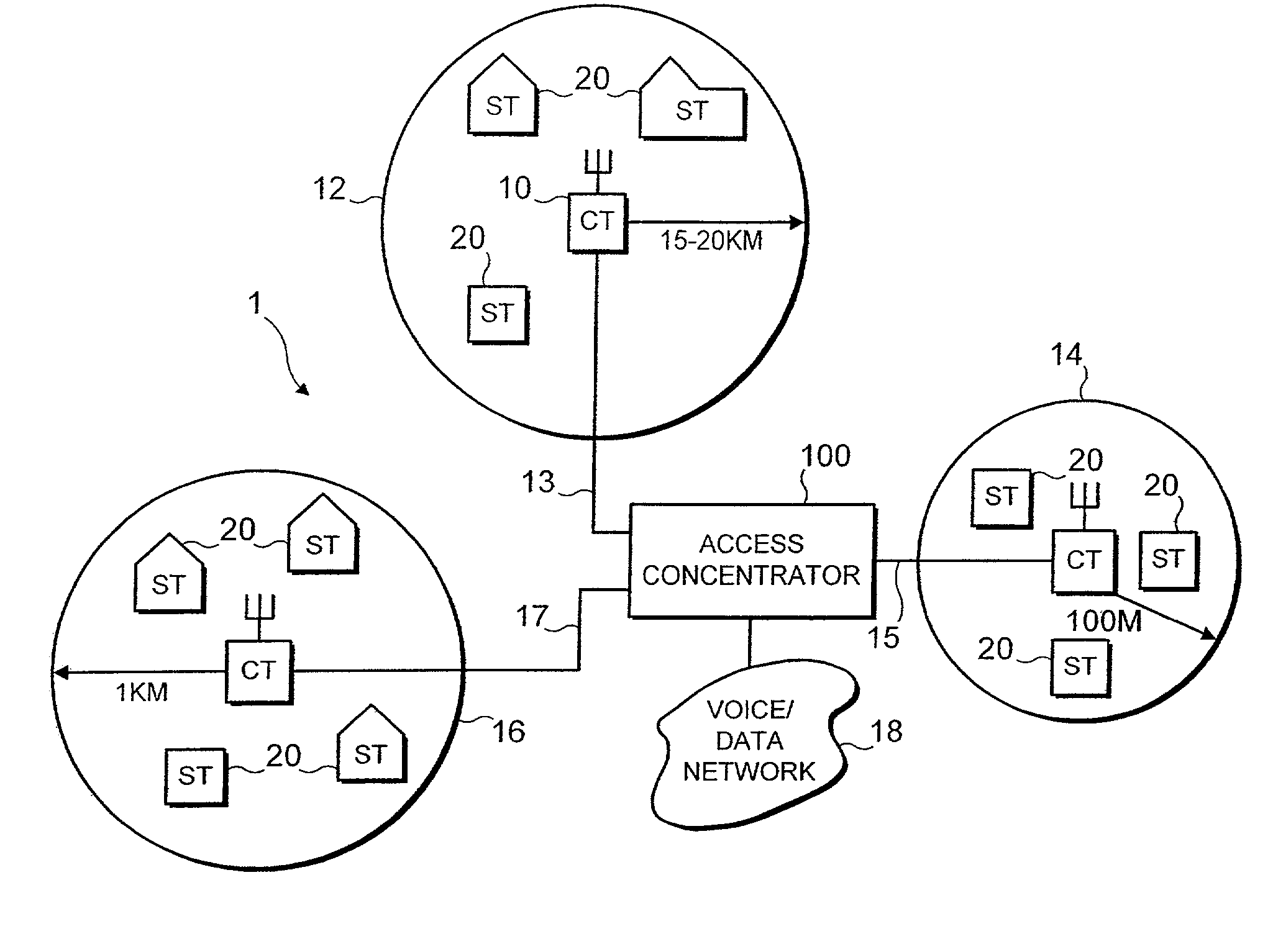
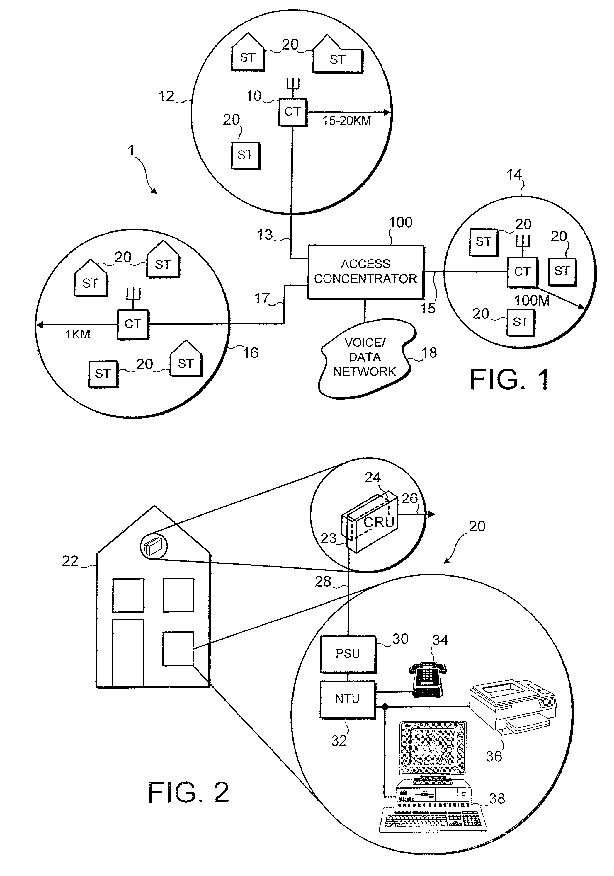
[0052] FIG. 1 is a schematic overview of an example of a wireless telecommunications system. The telecommunications system includes one or more service areas 12, 14 and 16, each of which is served by a respective central terminal (CT) 10 which establishes a radio link with subscriber terminals (ST) 20 within the area concerned. The area which is covered by a central terminal 10 can vary. For example, in a rural area with a low density of subscribers, a service area 12 could cover an area with a radius of 15-20 Km. A service area 14 in an urban environment where there is a high density of subscriber terminals 20 might only ...


PUM


Abstract

The present invention provides a telecommunications system and method for connecting to a network and for routing data messages between the network and subscriber terminals of the telecommunications system. The subscriber terminals are connectable to a central terminal of the telecommunications system via a transmission medium, with the telecommunications system providing a number of communication channels arranged to utilise the transmission medium for transmission of data between the central terminal and the subscriber terminals. The telecommunications system comprises a transmitter within the central terminal for sending a data message destined for a particular subscriber terminal over at least one of the communication channels as a number of data blocks. Further, a frame generator is provided within the central terminal for generating a number of frames to represent each data block, each frame having a header portion and a data portion. The header portion is arranged to be transmitted in a fixed format chosen to facilitate reception of the header portion by each subscriber terminal, and is arranged to include a number of control fields for providing information about the data portion. In contrast, the data portion is arranged to be transmitted in a variable format selected based on predetermined criteria relevant to the particular subscriber terminal to which the data portion is destined. This approach provides a particularly flexible and efficient technique for transmitting data within the telecommunications system.

Description

[0001] 1. Field of the Invention[0002] The present invention relates to the transfer of data in a telecommunications system, and more particularly to the routing of data between a network connectable to the telecommunications system and subscriber terminals of the telecommunications system.[0003] 2. Description of the Prior Art[0004] In a typical telecommunications system, a subscriber terminal may be located at a subscriber's premises for handling transfer of data to and from that subscriber. One or more lines may be provided from the subscriber terminal for supporting one or more items of telecommunications equipment located at the subscriber's premises. Alternatively, the subscriber terminal may be an integral part of the item of telecommunications equipment. Further, a central terminal may be provided for controlling a number of subscriber terminals, and in particular for managing transfer of data between a subscriber terminal and other components of a telecommunications network...

Claims


Application Information

Patent Timeline
Patent Type & Authority Applications(United States)
IPC IPC(8): H04B7/005H04L1/00H04B7/26H04J13/00H04L12/28H04L12/56H04Q11/04
CPCH04L1/0005H04W72/10H04L12/2856H04Q11/04H04Q2213/13141H04Q2213/13174H04Q2213/13204H04Q2213/13216H04Q2213/13298H04Q2213/13386H04Q2213/13389H04W40/02H04W52/58H04W72/08H04L1/0011Y02D30/70H04W72/54H04W72/56
Inventor LYSEJKO, MARTINCOHEN, JEREMY LAURENCE
Owner WI LAN INC
Why Eureka
Try Eureka