Tamp assembly

a technology of tamps and parts, applied in the field of tamps, can solve the problems of filler material being loosened or otherwise disturbed, using a plurality of separate tamps,

Inactive Publication Date: 2002-05-30
DUPUY INT LTD
View PDF0 Cites 16 Cited by
  • Summary
  • Abstract
  • Description
  • Claims
  • Application Information

AI Technical Summary

Problems solved by technology

A disadvantage of using a plurality of separate tamps can arise when a tamp has to be removed from within the bone cavity to be rep

Method used


Image

  • Tamp assembly
  • Tamp assembly
  • Tamp assembly

Examples


Embodiment Construction

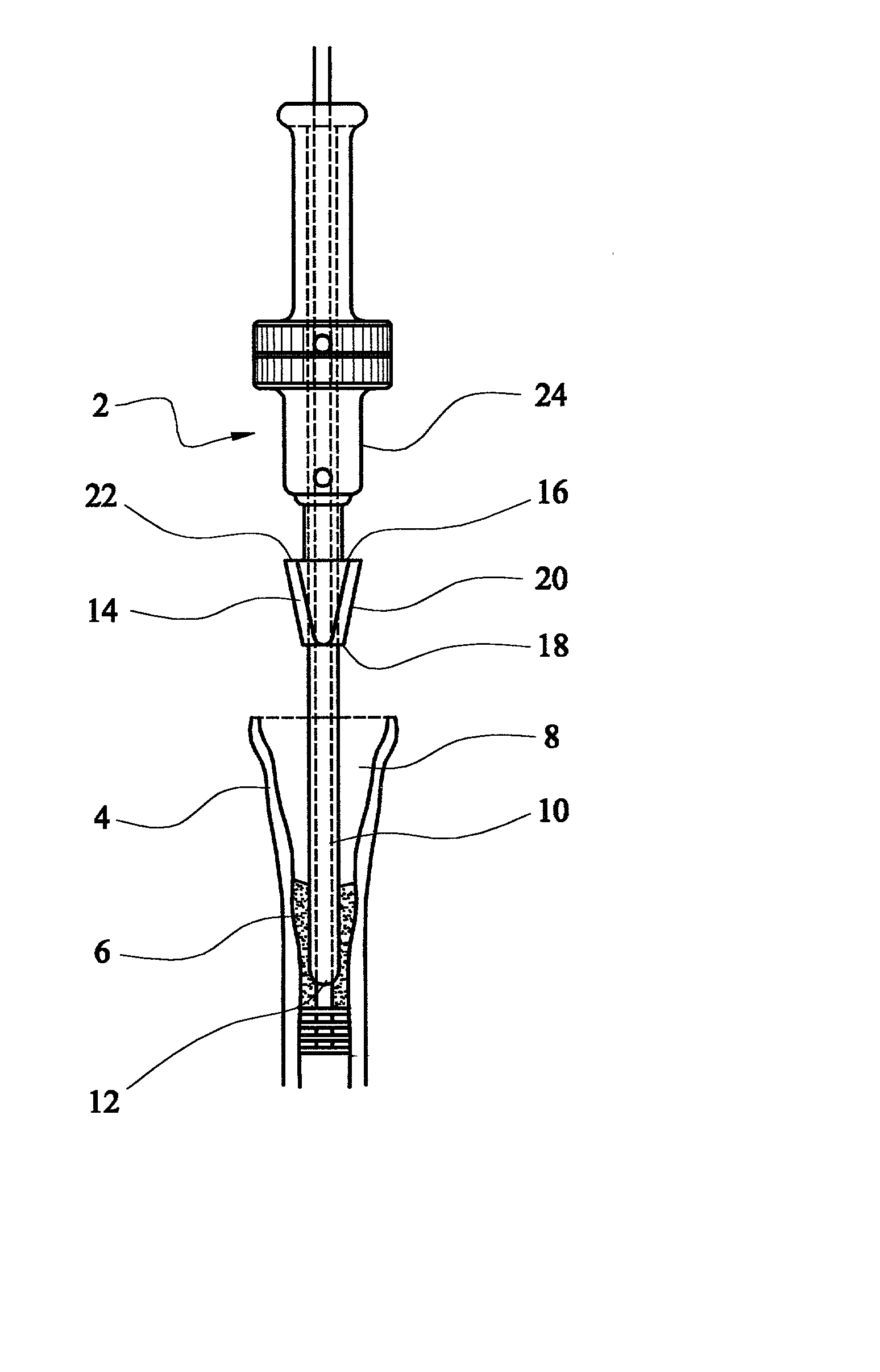
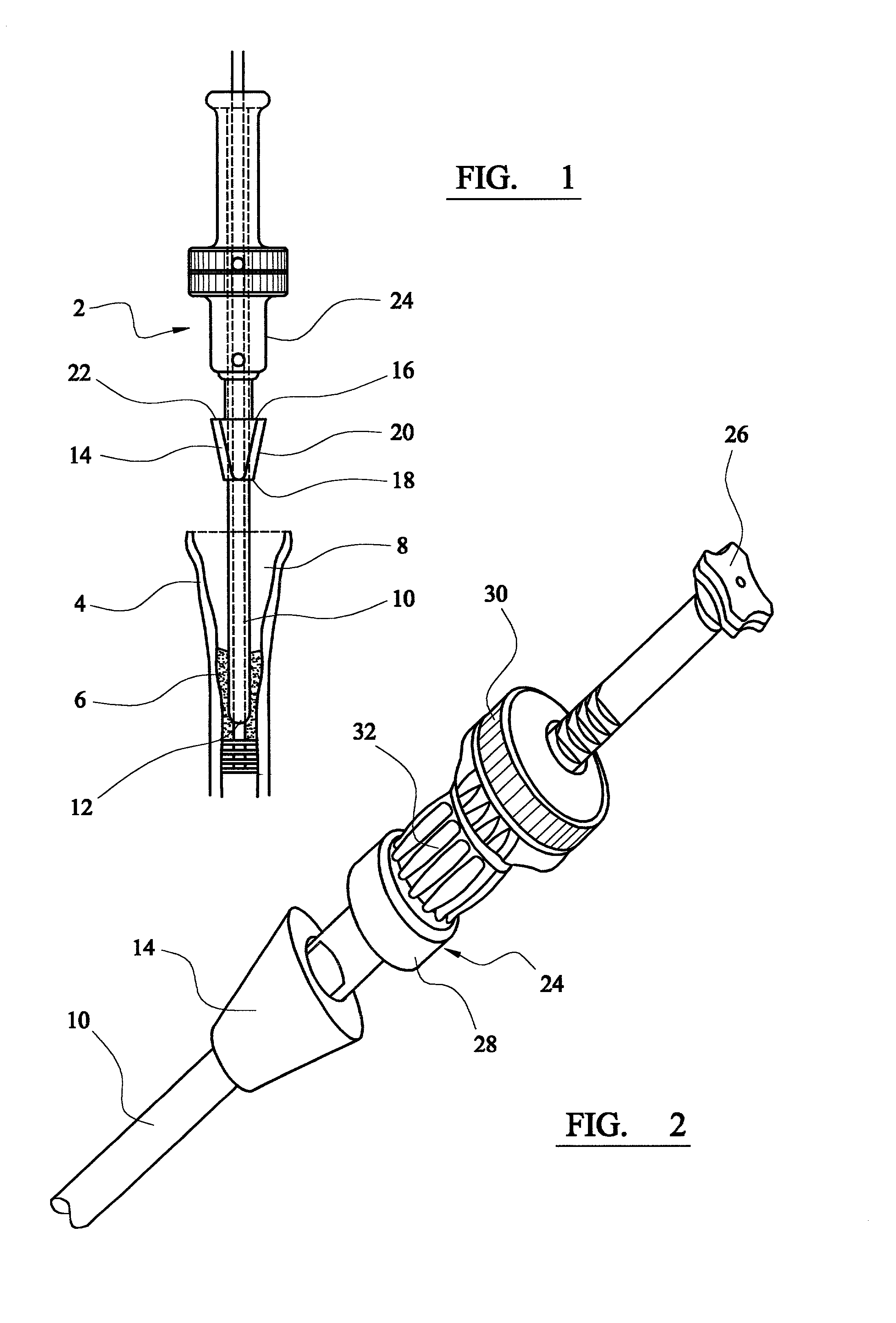
[0029] FIG. 1 shows a tamp assembly 2 positioned relative to a resected tibia 4 so as to tamp morcellised bone graft material 6 into the cavity 8 within the tibia, to receive the tibial component of a prosthetic knee joint.

[0030] The assembly includes a distal tamp portion 10 which has a substantially constant circular cross-section with a diameter which corresponds approximately to the internal dimensions of the bone cavity. For a typical patient, the tamp diameter will be about 10 mm. The distal tamp portion extends continuously over a length of about 40 cm and has a substantially constant cross-section over that length. The end 12 of the distal tamp portion is rounded.

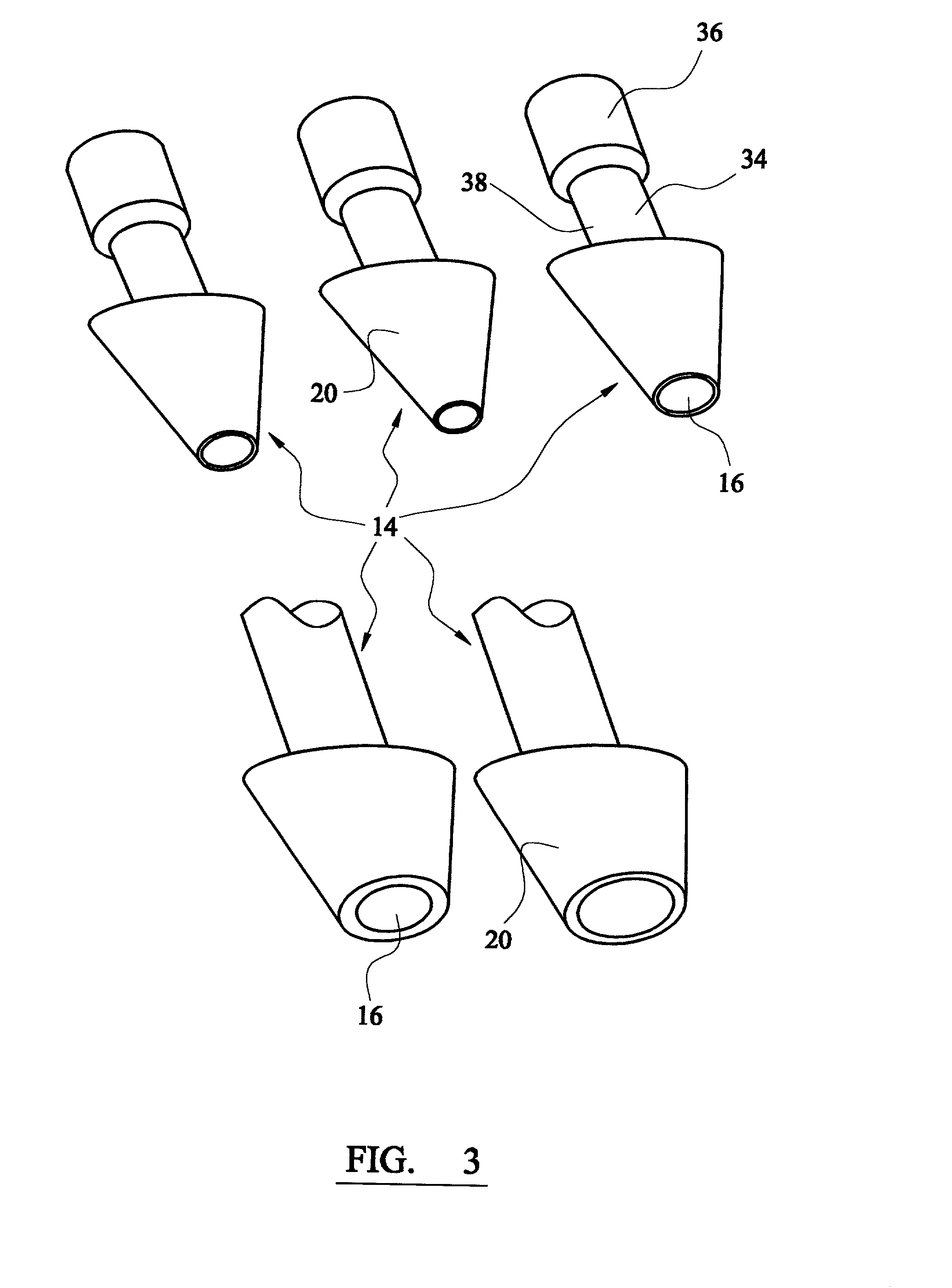
[0031] A proximal tamp portion 14 has a through bore 16 extending through it, so that it can receive the distal tamp portion 10 to extend through it. The proximal tamp portion has an external cross-section at its distal end 18 which is approximately the same as the external cross-section of the distal tamp portion. ...


PUM


Abstract

A tamp assembly for use in configuring bone cavity filler material within a bone cavity, in preparation for receiving an implant, includes a distal tamp portion which has a substantially constant cross-section over at least part of its length. A proximal tamp portion has a through bore extending through it with a size which is such that the proximal tamp portion is a sliding fit over the distal tamp portion. The proximal tamp portion has an exterior tamping surface extending from the through bore which faces generally towards the distal tamp portion. The assembly includes a hammer for transmitting impact to the bone cavity filler material which is contacted by the tamping surface of the proximal tamp portion.

Description

BACKGROUND TO THE INVENTION[0001] This invention relates to a tamp assembly for use in configuring bone cavity filler material within a bone cavity, in preparation for receiving an implant.[0002] It can be necessary to prepare a bone cavity to receive an implant during replacement of a bone joint. For example, the cavity within a femur has to be prepared to receive the femoral component of a hip joint prosthesis and cavities within the femur and tibia have to be prepared to receive respective components of a knee joint prosthesis.[0003] Joint prosthesis components can be fixed within a bone cavity by means of bone cement materials. They can also be fixed within a bone cavity by relying on the natural bone tissue, especially by providing the components with an appropriate surface finish which promotes bone ingrowth.[0004] It can be important to configure the cavity so that the prosthesis component fits into it with minimum space left empty within the cavity around the component. For ...

Claims


Application Information

Patent Timeline
IPC IPC(8): A61F2/00A61F2/28A61F2/30A61F2/36A61F2/38A61F2/46
CPCA61F2/30723A61F2/3662A61F2/3676A61F2/389A61F2/4601A61F2002/2835A61F2250/0064A61F2002/30726A61F2002/30797A61F2002/4602A61F2002/4623A61F2002/4624A61F2002/4681A61F2002/30616A61F2/4603
Inventor NAYBOUR, JOHNMOORE, DAVID
Owner DUPUY INT LTD
Why Eureka
Try Eureka