Robust diameter-controlled optical fiber during optical fiber drawing process

a technology of optical fiber and drawing process, which is applied in the direction of glass making apparatus, manufacturing tools, instruments, etc., can solve the problems of not robustly maintaining a high accuracy, the diameter of the optical fiber is still not robustly controlled, and the size of the optical fiber is not sufficient for a good control of the diameter of the fiber

Inactive Publication Date: 2002-06-06
BEN SHENG TECH
View PDF8 Cites 18 Cited by
  • Summary
  • Abstract
  • Description
  • Claims
  • Application Information

AI Technical Summary

Problems solved by technology

However, it may not robustly maintain a high accuracy due to many disturbance factors, perturbations, and environment changes, as well as drawing speed level changes mentioned in the following paragraph.
However, it is noticed that the diameter of the optical fiber is still not robustly controlled.
U.S. Pat. No. 5,443,610/1995 recognizes that the first measurement of the fiber diameter made on bare fiber in the region of the preform root, i.e., below the furnace, using an interference technique is not sufficient for a good control for the fiber diameter in view of error due to the fluctuation in the root with tractor speed.
However, it is still lack of a high accuracy measurement of the finished bare fiber diameter

Method used


Image

  • Robust diameter-controlled optical fiber during optical fiber drawing process
  • Robust diameter-controlled optical fiber during optical fiber drawing process
  • Robust diameter-controlled optical fiber during optical fiber drawing process

Examples


third embodiment

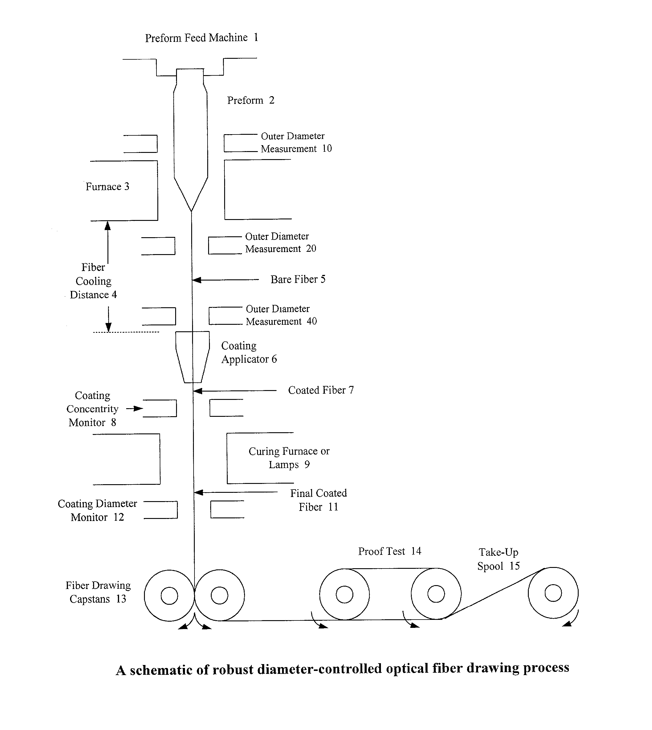
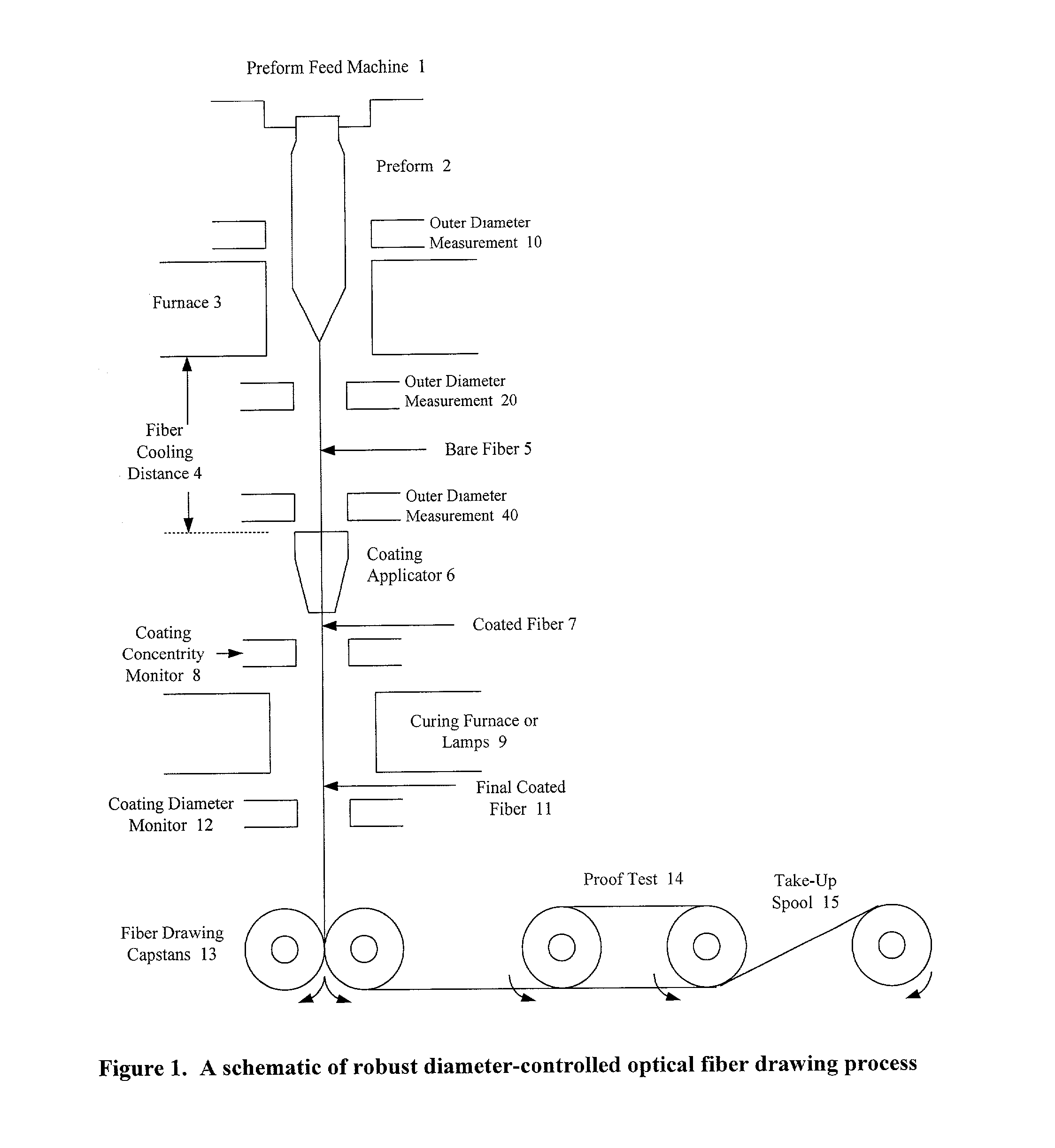
[0108] the present invention is shown in FIG. 3, in which two outer diameter monitors above the coating device are monitor 10 for the preform diameter measurement at a position safely and immediately above the furnace 3, and monitor 40 for the outer diameter measurement of the finished bare fiber at a position safely and immediately above the coating device. They provide control system feedback signals to the fiber drawing process control system for producing high quality optical fibers.

fourth embodiment

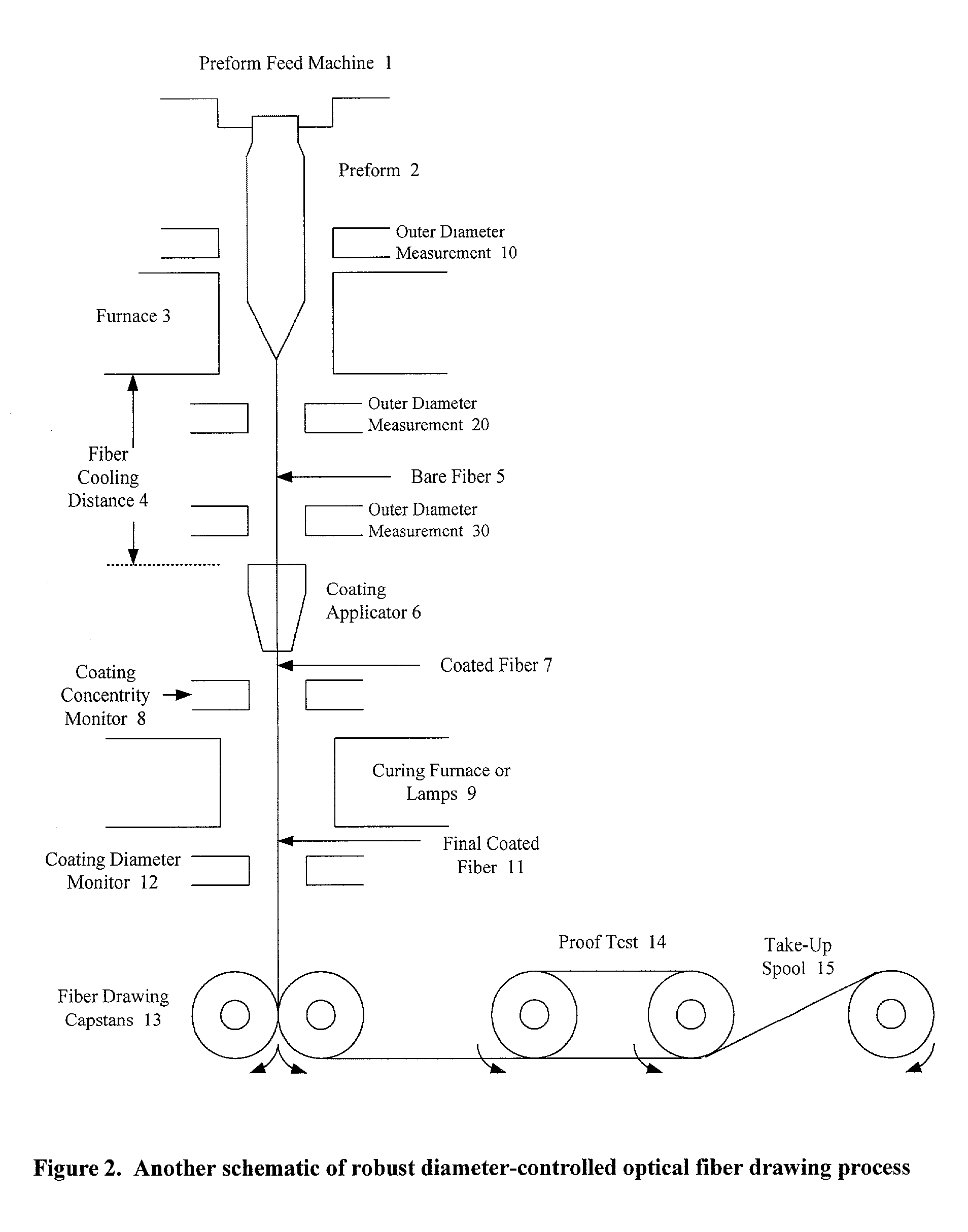
[0109] the present invention is shown in FIG. 4, in which two outer diameter monitors above the coating device are monitor 10 for the preform diameter measurement at a position safely and immediately above the furnace 3, and monitor 30 at a position with a shrinkage ratio less than 0.5%. The control system collects these measurement data and determines the fiber drawing speed and the preform feeding speed.

[0110] A further embodiment of the present invention shown in FIG.5 is to let monitor 30 in FIG.4 can be adjusted based on the drawing speed, high or low. In the embodiment as shown in FIG. 4, it takes time to detect the outer diameter of the fiber which is under increase in its diameter in the case of small drawing rate, whereby a time lag arises in the control. In the embodiment as shown in FIG. 5, when the drawing rate is small, detection of the outer diameter is carried out with the measuring device 31 and when the rate is increased, the detection is carried out with the measur...

sixth embodiment

[0111] the present invention is shown in FIG. 6, in which two outer diameter monitors above the coating device are monitor 10 for the preform diameter measurement at a position safely and immediately above the furnace 3, and monitor 20 for the outer diameter measurement of the bare fiber at a position safely and immediately below the furnace 3. The control system collects these measurement data and determines the fiber drawing speed and the preform feeding speed.

[0112] Monitor 20 has the smallest time lag than monitor 30 (or 31 or 32), especially when the drawing speed is low. Monitor 30 provides a higher accuracy of the out diameter of the optical fiber than monitor 20 when the drawing speed is high. However, monitor 40 has the highest accuracy of outer diameter measurement for the finished bare fiber, i.e., the optical fiber glass diameter.

[0113] A further variation of embodiments of the present invention is shown in FIG. 7, in which two outer diameter monitors between the furnace...


PUM

PropertyMeasurementUnit
Shrinkageaaaaaaaaaa
Diameteraaaaaaaaaa
Sizeaaaaaaaaaa

Abstract

There is provided robust diameter-controlled optical fiber during optical fiber drawing process and an optical fiber drawing process which comprises drawing the optical fiber from a perform therefor under tension to form the optical fiber while heating and melting the preform, wherein an outer diameter of the preform is measured (at a safe position immediately) above the furnace, an outer diameter of the optical fiber on which no coating has been provided is measured at one process position or two process positions before coating, and drawing conditions are robustly controlled based on the deviation of the measured optical fiber diameter data and the measured preform diameter data from a preselected outer diameter of the optical fiber and a preselected outer diameter of the preform.

Description

[0001] 1. Field of the Invention[0002] The present invention relates to optical fibers and a process for optical fiber drawing.[0003] 2. Description of the Related Art[0004] Optical fiber drawing process is an important period of optical fiber manufacturing.[0005] A conventional drawing process of optical fiber is as follows. A completed preform is fed slowly into a furnace where the preform end is heated to about 2000.degree. C. and soften. The soften glass forms a globule falling down from the furnace, through the other stages of the drawing process and onto a take-up spool. The stages thereof are outer diameter measurement, fiber cooling stage, fiber coating stage, coating concentrity measurement, curing stage, coating diameter measurement, fiber drawing capstans, proof test and winding on take-up spool. The feeding speed depends on the furnace design, preform diameter and draw speed. The optical fiber which has just left the furnace and is remaining intact is called "bare fiber"...

Claims


Application Information

Patent Timeline
IPC IPC(8): C03B37/025
CPCC03B2205/40C03B37/0253Y02P40/57
Inventor WANG, SHENG-GUO
Owner BEN SHENG TECH
Why Eureka
Try Eureka