Rotary electric machine with stacked brush
- Summary
- Abstract
- Description
- Claims
- Application Information
AI Technical Summary
Problems solved by technology
Method used
Image
Examples
first embodiment
[0031] (First Embodiment)
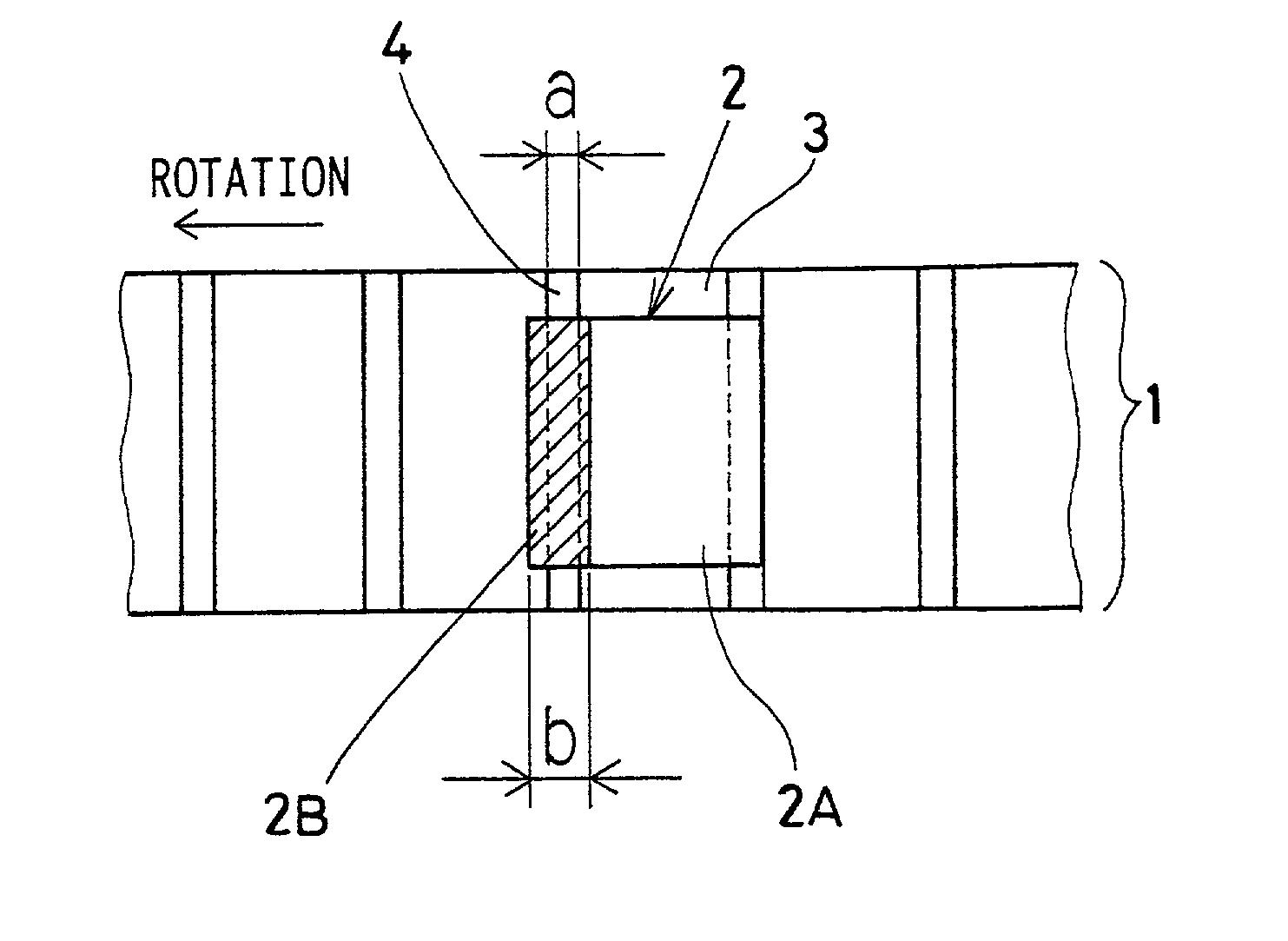
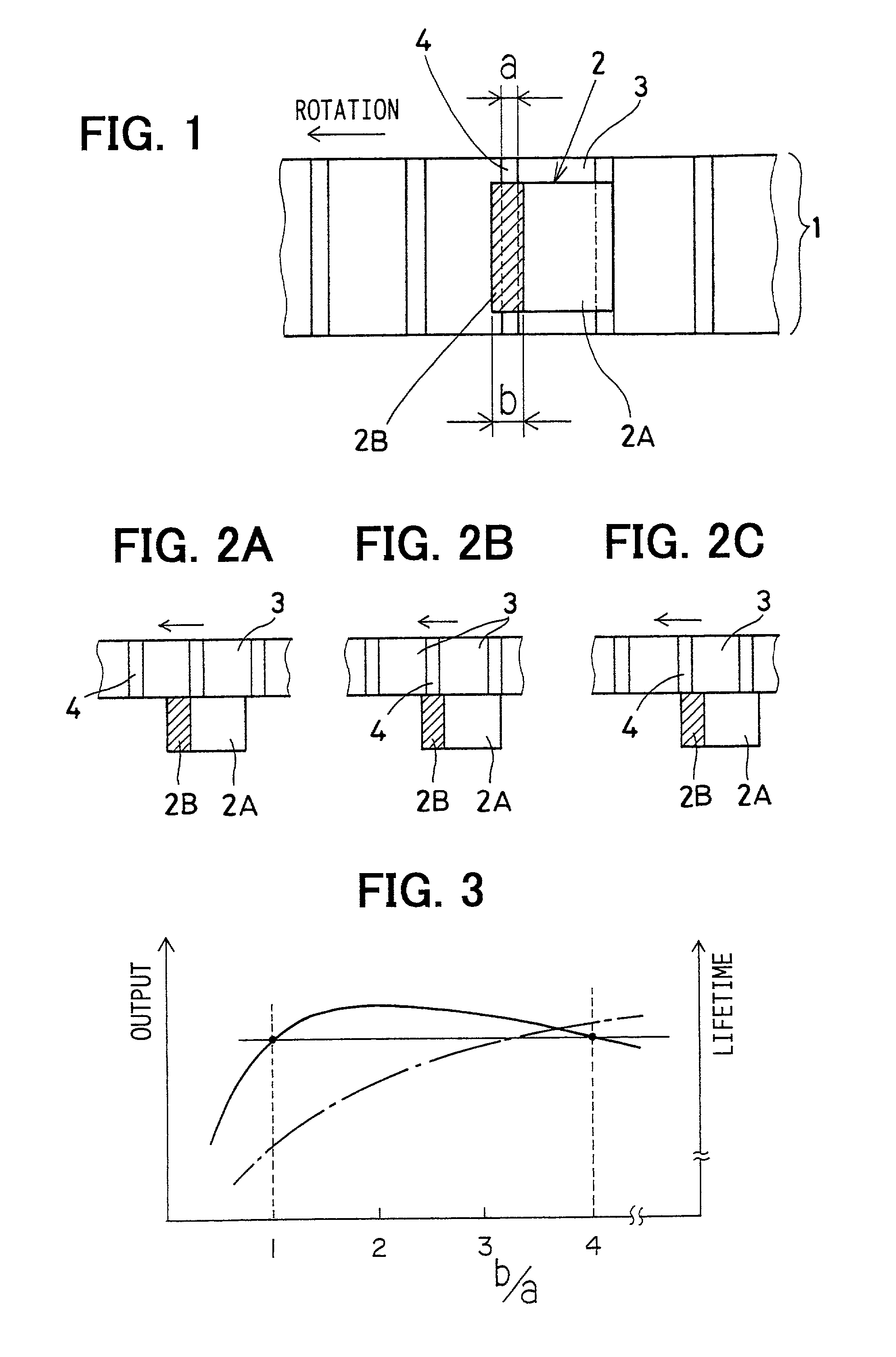
[0032] In FIG. 1, a brush 2 is disposed on a commutator 1 provided in an armature. A motor current is supplied to the armature through the commutator 1 and the brush 2.
[0033] The commutator 1 includes plural conductive segments 3, which are arranged in a cylindrical shape while a given gap as an undercut portion 4 remains between neighboring segments 3 for insulation. Each segment 3 is connected to an armature coil (not shown) wound around the armature.
[0034] The brush 2 is formed by layering a low-resistance brush layer 2A and a high-resistance brush layer 2B each having different specific resistance. The low-resistance brush layer 2A is disposed at the front end side in the rotational direction (arrow direction) of the commutator 1. The high-resistance brush layer 2B is disposed at the rear end side in the rotational direction.
[0035] The insulation gap (undercut portion 4) provided between the neighboring segments 3 of the commutator 1 has a width "a", and...
second embodiment
[0042] (Second Embodiment)
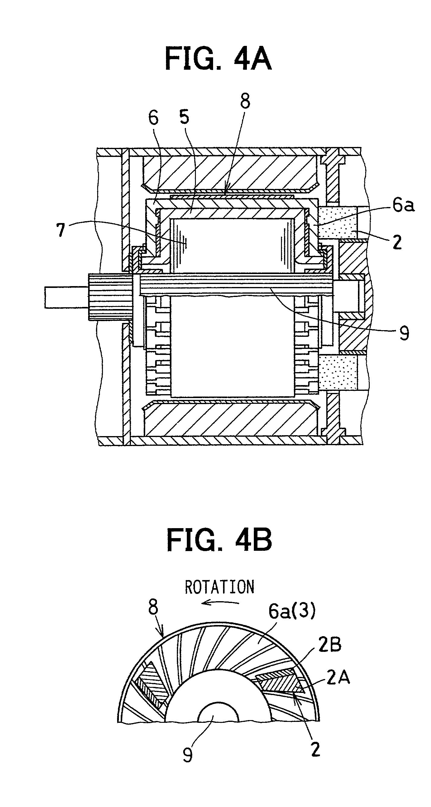
[0043] In the rotary electric machine in a second embodiment, as shown in FIG. 4A, an armature coil is formed by attaching plural inner-layer coil segments 5 and plural outer-layer coil segments 6, which are U-shaped, to a core 7 and by brazing both coil segments 5, 6 in order. Further, a surface-type commutator is constructed by coil end portions 6a each provided as each segment 3 at the end of each outer-layer coil segment 6. The surface-type commutator is provided so that each segment 3 (coil end portion 6a of the outer-layer coil segment 6) is perpendicular to a rotational shaft 9 of an armature 8. The brush 2 comes in contact with each segment 3 in the axial direction. As in shown in FIG. 4B, the low-resistance brush layer 2A is disposed at the front side in the rotational direction of the armature 8, and the high-resistance brush layer 2B is disposed at the rear side in the rotational direction.
[0044] In this rotary electric machine, too, as in the fi...
third embodiment
[0046] (Third Embodiment)
[0047] In a third embodiment, as shown in FIG. 5, the segment 3 has the circumferential width "c", and the insulation portion (undercut portion 4) has the width "a" as in the first embodiment. The high-resistance brush layer 2B has the stack direction width "b" as in the first embodiment, and the low-resistance brush layer 2A has the stack direction width "d". The following relationships are satisfied among these dimensions.
b+d>2.times.a+c (3)
d>b (4)
a
d
[0048] That is, the brush 2 has the size to come in contact with three segments, sequentially arranged in the circumferential direction, at a maximum at the same time. The stack direction width of the low-resistance brush layer 2A is set larger than the stack direction width of the high-resistance brush layer 2B. The high-resistance brush layer 2B has the width to come in contact with the segments 3 at both front and rear sides of the undercut portion 4 at the same time.
[0049] Next, operation and ...
PUM
 Abstract
Description
Claims
Application Information
 - R&D
- Intellectual Property
- Life Sciences
- Materials
- Tech Scout
- Unparalleled Data Quality
- Higher Quality Content
- 60% Fewer Hallucinations
Browse by: Latest US Patents, China's latest patents, Technical Efficacy Thesaurus, Application Domain, Technology Topic, Popular Technical Reports.
© 2025 PatSnap. All rights reserved.Legal|Privacy policy|Modern Slavery Act Transparency Statement|Sitemap|About US| Contact US: help@patsnap.com


