
Zero-crossing point commutator and zero-crossing point commutation control method for permanent magnet brushless DC motor

A permanent magnet brushless DC, zero-crossing technology, applied in the direction of electronically commutated motor control, control system, monitoring commutation, etc., can solve the problems of high rotor speed, lower system reliability, and magnetic pole distribution errors, etc., to achieve Strong environmental adaptability, easy control of speed, and increased reliability

Inactive Publication Date: 2019-06-21
湖南长高思瑞自动化有限公司
View PDF6 Cites 11 Cited by
  • Summary
  • Abstract
  • Description
  • Claims
  • Application Information

AI Technical Summary

Problems solved by technology

[0005] ① Due to the high speed of the rotor of the high-speed motor, which can reach hundreds of thousands of revolutions per minute, the detection accuracy of the rotor position sensor will decrease at high speed;
[0006] ②The sensor itself and the signal processing circuit will increase the volume and cost of the system, thereby reducing the reliability of the system;
[0007] ③High-speed motors require the rotor to be as short as possible to ensure that the rotor has sufficient mechanical strength and rigidity to increase its resonance frequency, so installing a position sensor will increase the difficulty of rotor design
[0010] Directly installing the Hall sensor has the advantage of easy installation, but it is impossible to adjust the reversing point trigger point to advance or delay; therefore, all parameters of the motor must be designed accurately, otherwise the rated speed or rated power may not be reached
To install the Hall sensor separately, the Hall sensor needs to be distributed according to the electrical angle of 120°. Generally, it is made into a ring-shaped printed circuit board, which requires an independent magnetic ring. The magnetic ring should not only have the same number of magnetic poles as the motor rotor, but also from the In principle, the magnetic pole distribution on the magnetic ring and the magnetic pole distribution of the brushless DC motor rotor should also be the same, but due to the limitation of the magnetization process, there is actually an error between the magnetic pole distribution of the magnetic ring and the magnetic pole distribution of the motor rotor, which is to a certain extent On the other hand, it affects the further improvement of the performance of the permanent magnet brushless DC motor
In addition, for the Hall sensor installed separately, the motor commutation trigger point is fine-tuned by rotating and adjusting the Hall sensor printed circuit board. Such adjustment can only be made during the motor assembly process; The trigger point cannot be changed, which directly limits the speed range of the brushless DC motor
However, in air conditioner compressors, due to the strong corrosiveness of the refrigerant, it is even difficult for conventional position sensors to work normally. Therefore, it is necessary to study a reliable, low-cost control method without position sensors.

Method used


Image

  • Zero-crossing point commutator and zero-crossing point commutation control method for permanent magnet brushless DC motor
  • Zero-crossing point commutator and zero-crossing point commutation control method for permanent magnet brushless DC motor
  • Zero-crossing point commutator and zero-crossing point commutation control method for permanent magnet brushless DC motor

Examples


Embodiment Construction

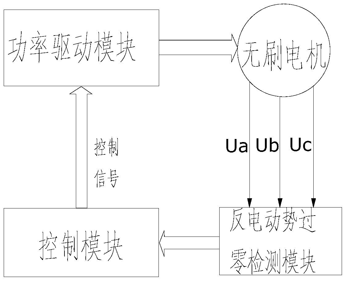
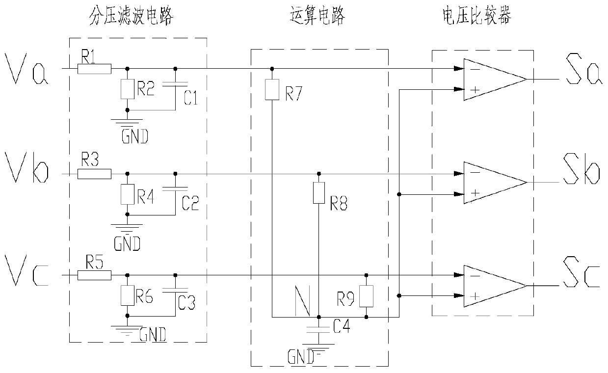
[0032] like figure 1 As shown, it is a zero-crossing commutator of a permanent magnet brushless DC motor of the present invention, which includes a counter electromotive force detection module, a control module, and a power drive module that are electrically connected in sequence; wherein, the counter electromotive force detection module is used for Obtain the stator voltage information of the permanent magnet brushless DC motor to detect the zero-crossing signal of the back electromotive force;

[0033] The control module is used to determine the optimal commutation point according to the back electromotive force zero-crossing signal, and output a PWM control signal to the power drive module;

[0034] Specifically, the control module takes the Stm32 single-chip microcomputer as the core, uses the on-chip AD to directly sample the three-phase terminal voltage of the motor, and judges the zero-crossing point of the reverse electromotive force of the levitation phase through the...


PUM


Abstract

The invention discloses a zero-crossing point commutator for a permanent magnet brushless DC motor. The zero-crossing point commutator for the permanent magnet brushless DC motor comprises a counter electromotive force detection module, a control module and a power drive module which are electrically connected in sequence, wherein the counter electromotive force detection module is used to acquirestator voltage information of the permanent magnet brushless DC motor, so as to detect a counter electromotive force zero-crossing signal; the control module is used to determine the optimum commutation point according to the counter electromotive force zero-crossing signal, and output a PWM control signal to the power drive module; and the power drive module is used to control the commutation ofthe permanent magnet brushless DC motor according to the PWM control signal. The zero-crossing point commutator for the permanent magnet brushless DC motor disclosed by the invention has the advantages that a modular design is adopted, so that the zero-crossing point commutator achieves a simple structure, and can be independently packaged and directly installed and applied for motor control; andthrough a sensorless control mode, the motor can achieve high energy conversion efficiency, high environmental adaptability, higher reliability and lower cost.

Description

technical field [0001] The invention relates to a permanent magnet brushless DC motor, in particular to a zero-crossing commutator and a control method of the permanent magnet brushless DC motor. Background technique [0002] Motor control is the control of starting, accelerating, running, decelerating and stopping the motor. There are different requirements and purposes according to the type of motor and the application occasion of the motor. [0003] The motor body of the brushless DC motor is similar to the structure of a permanent magnet synchronous motor. The stator is an armature, and the rotor is a permanent magnet. The use of rare earth permanent magnet materials greatly reduces the weight of the brushless DC motor, simplifies the structure, and improves the efficiency. Compared with ordinary DC motors, it removes the mechanical contact structure composed of commutator and brush, and adopts electronic switch commutation device to improve its reliability. When a cer...

Claims


Application Information

Patent Timeline
IPC IPC(8): H02P6/182H02P6/12
Inventor 雷波周显俊刘堂伟唐友丽
Owner 湖南长高思瑞自动化有限公司
Learn More