A motor coil winding structure

A motor and coil technology, applied in the shape/style/structure of winding conductors, etc., can solve the problems of rising manufacturing costs, waste of coils, etc., and achieve the effects of saving manufacturing costs, reducing logistics costs, and reducing size and weight

Active Publication Date: 2015-04-15
HYO SEONG ELECTRIC
View PDF5 Cites 12 Cited by
  • Summary
  • Abstract
  • Description
  • Claims
  • Application Information

AI Technical Summary

Problems solved by technology

[0002] In general, in various motors, a commutator and a core are wound with a coil, an electric current is supplied from the outside, and the shaft is rotated by a magnetic field with a magnet to convert electrical energy into rotation. The kinetic energy of the DC motor, such as the conventional automobile brake motor, supplies current to the coil wound on the segment of the commutator and the slot of the core through the brush. At this time, according to the method of winding the coil on the slot of the core, it is roughly divided into concentrated winding and distributed winding. It is a winding method in which the coil is wound separately in 3 to 5 slots. As far as the distributed windings included in the coil winding method of the present invention are concerned, such as Korean Publication No. 2006 No. 79147 (July 2006) has been developed. 5th) or various winding methods such as the lap winding disclosed in Korean Laid-Open Patent No. 1519 of 1994 (published on January 11, 1994), but There are many problems. When the coil is wound in such a conventional wave winding or lap winding method, the pitch (pitch) between the slots of the core is 3 or more, and the coil is wound, so that the coils of the conventional distributed winding Due to the winding structure of the coil, the coil is excessively overlapped on the upper and lower parts of the core, which leads to the waste of the coil and has the disadvantage of increasing the manufacturing cost. At the same time, a large number of coils are repeatedly wound, resulting in an increase in the volume and weight of the motor, which increases the manufacturing cost. At the same time, there is a disadvantage economically due to the increase in logistics costs due to the transportation of the heavy motor. In addition, the resistance of the longer coil increases and the copper loss (copper loss) increases, which has the disadvantage of reducing the efficiency of the motor.

Method used


Image

  • A motor coil winding structure
  • A motor coil winding structure
  • A motor coil winding structure

Examples


Embodiment Construction

[0020] Hereinafter, the present invention will be described in more detail with reference to the drawings.

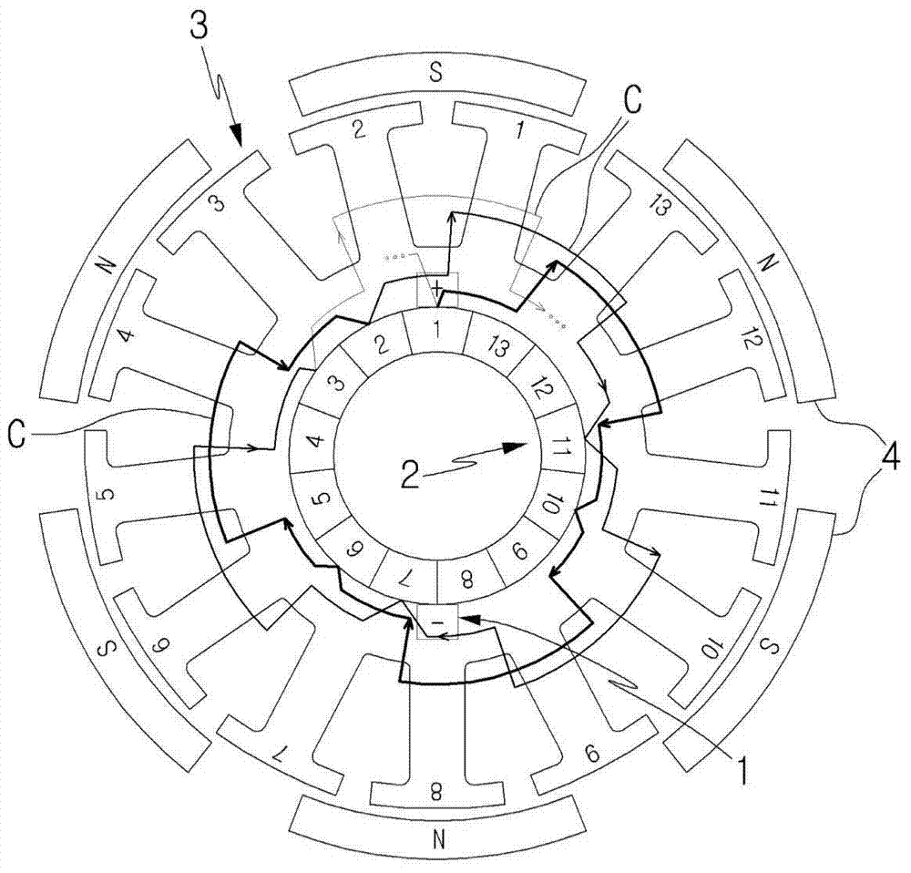
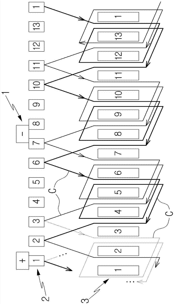
[0021] The invention relates to a coil winding structure in various electric motors comprising: a brush (1) equipped with coils for winding to the slots of the laminations of the commutator (2) and the core (3) (C) Supply current to obtain rotational force; commutator (2), which contacts brush (1), transmits current to coil (C); and iron core (3), which is fixedly installed with commutator (2) on shaft; coil (C), which is wound on the pieces of the commutator (2) and the slot of the iron core (3); magnet (4), which is fixedly installed in the casing, and when the current flows through the coil wound on the iron core (3) In the case of (C), an armature composed of a commutator (2), an iron core (3) and a coil (C) attached to the shaft is rotated by a magnetic field.

[0022] The coil winding structure of the motor of the present invention is as follows Figures 1 to 2 ...


PUM


Abstract

The invention aims to provide a motor coil winding structure. After being led in a slot, a coil (C) from each segment of a commutator (2) to an iron core (3) side is led out to a slot with a 2-pitch interval from the slot and is wound on two teeth; in a motor, the coil is wound on the segments of the commutator (2) and the teeth and the slots of the iron core (3), the number of the segments of the commutator (2) of the motor is 13, the number of the teeth and the number of the slots of the iron core are 13, and the number of poles of a magnet (4) which is counterpoised to the outside of the iron core (3) is six; and thus, compared with a winding structure in the prior art which is wound with an interval of more than 3 pitches, the overall winding length and winding amount can be reduced, copper loss generated when a current flows through the coil (C) can be remarkably reduced, even if a coil (C) is wound with the amount less than that of a coil (C) of a motor in the prior art which is wound with an interval of more than 3 pitches set in the iron core (3), efficiency or more than the identity can be achieved, manufacturing cost is remarkably saved while motor efficiency is improved, and the size and the weight of the motor can be miniaturized.

Description

technical field [0001] The present invention aims to provide the coil winding structure of the motor. If it is described in more detail, it aims to provide an improved structure when the coil of the motor is wound into distributed windings, so that the coil is wound at 2-pitch intervals of the core, reducing the The consumption of the coil is reduced, so the coil winding structure of the motor can greatly save the manufacturing cost. Background technique [0002] In general, in various motors, a commutator and a core are wound with a coil, an electric current is supplied from the outside, and the shaft is rotated by a magnetic field with a magnet to convert electrical energy into rotation. The kinetic energy of the DC motor, such as the conventional automobile brake motor, supplies current to the coil wound on the segment of the commutator and the slot of the core through the brush. At this time, according to the method of winding the coil on the slot of the core, it is rou...

Claims


Application Information

Patent Timeline
Patent Type & Authority Applications(China)
IPC IPC(8): H02K3/12H02K3/28
CPCH02K3/12H02K3/28
Inventor 郑震根
Owner HYO SEONG ELECTRIC
Why Eureka
Try Eureka