Ultra power supply

a technology of electrical storage devices and batteries, applied in the direction of ohmic-resistance heating, transportation and packaging, indicating/monitoring circuits, etc., can solve the problems of high transient load unsuitability, high duty cycle, and difficult cell selection

Inactive Publication Date: 2012-04-19
INNOVATIVE WIRELESS TECH
View PDF0 Cites 11 Cited by
  • Summary
  • Abstract
  • Description
  • Claims
  • Application Information

AI Technical Summary

Benefits of technology

[0011]The present invention specifically addresses and alleviates the above mentioned deficiencies associated with the prior art. More particularly, the present invention in a first aspect, is a portable power supply comprising: a plurality of accumulator battery cells for providing power to a load via a main circuit; a charging circuit coupled to the plurality of accumulator batteries, the charging circuit separate from the main circuit supplying power to the load; a power supply commutator for optimally supplying varied amounts of power to the load as needed; and a microcontroller for proving programmable control of the supplying varied amount of power via the power supply commutator.

Problems solved by technology

For example, some constructions may be particularly well suited for supplying current at a consistent voltage over an extended period but unsuitable for high transient loads, whereas others are better suited for various changing loads.
In other applications, the duty cycle may vary dramatically and inconsistently making cell selection more difficult.
To further complicate the selection, many applications that require high peak currents also have volume and weight constraints, for example power tools, hobby planes and race carts to name a few.
For many of those applications that have high peak current requirements, the number of batteries required to satisfy the maximum peak current would not fit inside the available volume.
The switch makes it impossible to charge or discharge the battery cells during the extended non-use.

Method used


Image

  • Ultra power supply
  • Ultra power supply
  • Ultra power supply

Examples


Embodiment Construction

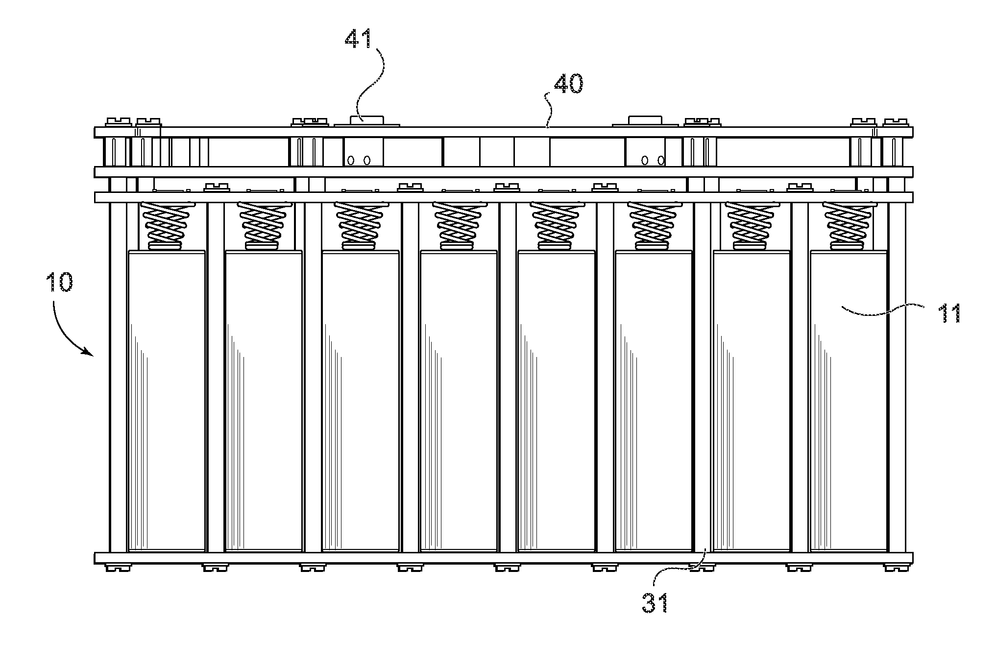
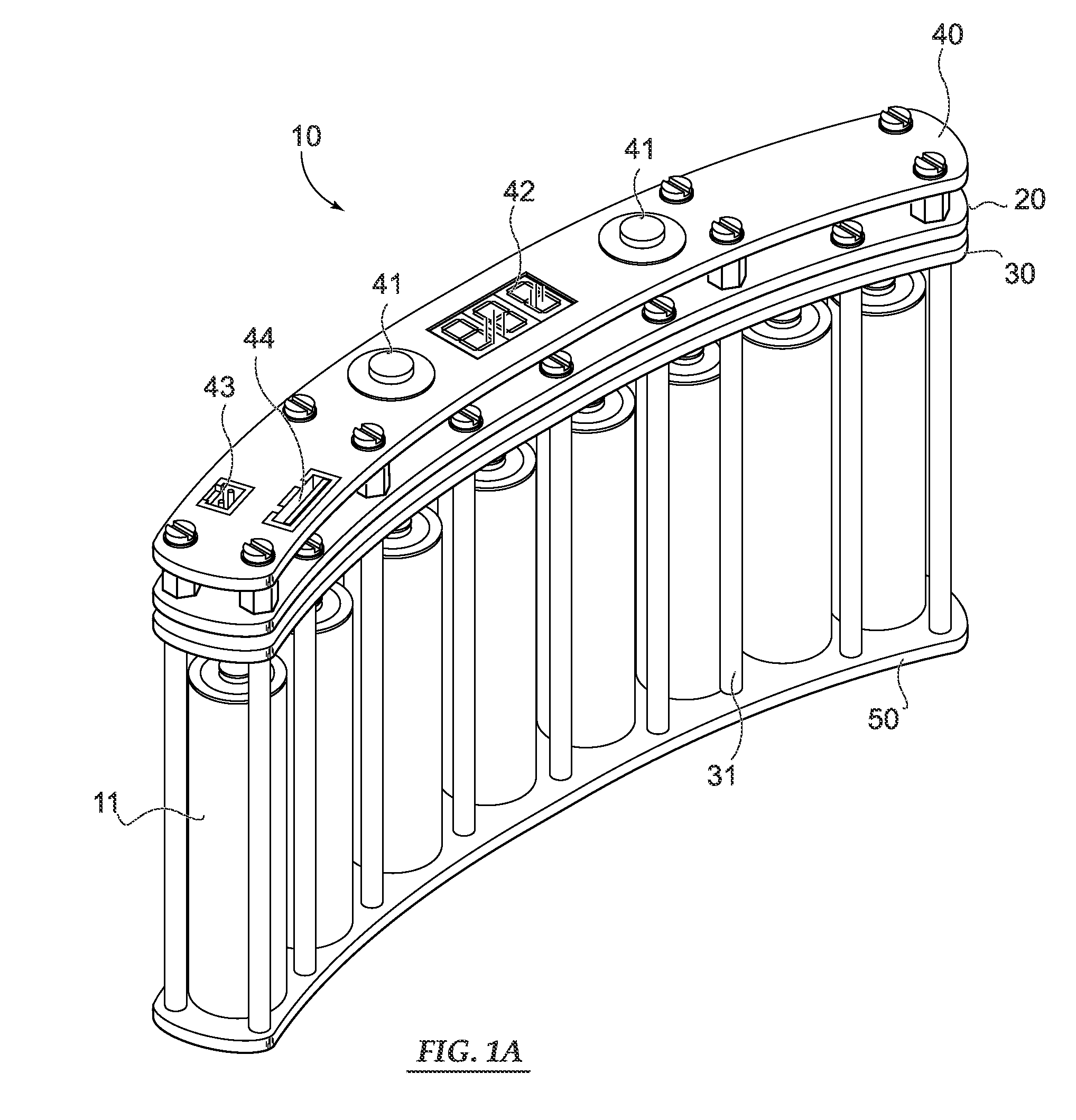
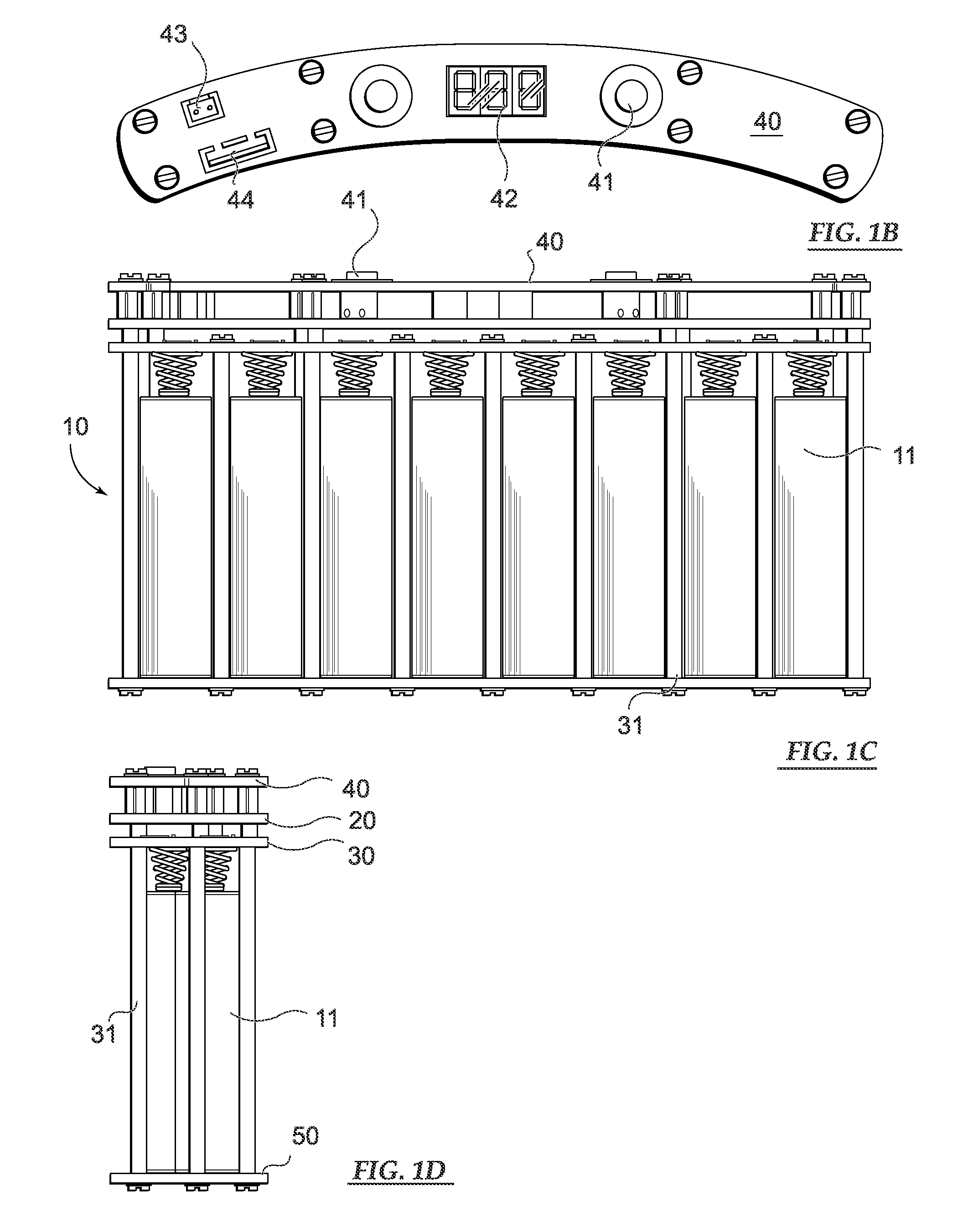
[0030]With regard to FIG. 1A, a perspective view of a bank of accumulator batteries forming a power supply 10 is illustrated. In this configuration, several printed circuit board layers 20, 30, 40, 50 form the power supply circuit also comprising electronics to achieve specific objectives of the present invention as disclosed herein. Development of the present invention 10 was motivated by a need for smaller, better, lighter-weight power sources for use by individual field operators. Importantly, the power supply 10 comprises a microcontroller 60 (FIG. 2) that provides control and monitoring 62 of accumulator characteristics and indications. In a preferred embodiment, the power supply further comprises four channels 44 coupled to four heating elements. The power supply 10 additionally comprises an antenna coupled to a transceiver 67 providing wireless control of the each individual channels 44. Also, the wireless Rf control functions reliably even underwater.

[0031]As shown and also ...


PUM


Abstract

An improved portable battery system having a plurality of accumulator batteries designed with circuit features to prolong life through cell balancing is disclosed. Further, the portable battery system is designed to be a lighter-weight alternative by use of individual field operators, for example, in colder climates configured to a heated garment. Additionally, the power supply includes a microcontroller that provides control and monitoring of accumulator properties. A power supply commutator is provided to aid efficient discharge of accumulators.

Description

PRIORITY CLAIM[0001]This patent application contains subject matter claiming benefit of the priority date of U.S. Provisional Patent Application Ser. No. 61 / 324,565 filed on Apr. 15, 2010 and entitled, ULTRA POWER SUPPLY, accordingly, the entire contents of this provisional patent application is hereby expressly incorporated by reference.BACKGROUND OF THE INVENTION[0002]1. Field of the Invention[0003]The present invention relates generally to rechargeable electrical storage devices and battery powered loads. More particularly, in a preferred embodiment, the present invention pertains to an advanced rechargeable power supply system that can monitor and manage a plurality of individual accumulator power supplies that further include a plurality of individual load channels; the preferred embodiment further supplies power to heating element(s).[0004]2. Description of the Art[0005]Conventional electrical power supply circuits for portable devices have been known in the art. Some simple e...

Claims


Application Information

Patent Timeline
Patent Type & Authority Applications(United States)
IPC IPC(8): H05B3/02H05B1/00H02J7/00
CPCH02J7/0014H02J7/0047H02J7/0021H02J7/0048
Inventor MIRONICHEV, SERGEI Y.MECHLING, CHRISTOPHER D.
Owner INNOVATIVE WIRELESS TECH
Why Eureka
Try Eureka