Eureka AIR delivers breakthrough ideas for toughest innovation challenges, trusted by R&D personnel around the world.

Catheter with enhanced reinforcement

a technology of enhanced reinforcement and catheter, which is applied in the direction of catheters, flexible pipes, intravenous devices, etc., can solve the problems of insufficient polymer mass of catheter walls and insufficient control of reinforcing braids, and achieves thin catheter walls, thin polymer layers, and minimal support

Inactive Publication Date: 2002-06-13
ABBOTT CARDIOVASCULAR
View PDF0 Cites 51 Cited by
  • Summary
  • Abstract
  • Description
  • Claims
  • Application Information

AI Technical Summary

Benefits of technology

[0011] The elongated catheter shaft may have varied properties along the length. Typically, the elongated catheter shaft has increased flexibility in the distal direction by forming the catheter wall with polymeric materials having decreasing stiffness, i.e. distally decreasing durometers.
[0017] Fixing the shape of the braided reinforcing structure by bonding or otherwise securing the crossed strands of the braided reinforcement strengthens the braided structure and minimizes the support the polymeric material must add to the catheter shaft structure. This allows for much thinner polymer layers, resulting in thinner catheter walls and provides for more supportive and consistent catheter shapes.

Problems solved by technology

These catheter design changes have required a reduction in the ratio of polymer to stranded reinforcement in the catheter wall which results in manufacturing problems with respect to the shaping of the distal end of the catheter.
With such thin polymeric walls, the polymer mass of the catheter wall can be insufficient to control the reinforcing braid within the wall to the desired shape.

Method used


Image

  • Catheter with enhanced reinforcement
  • Catheter with enhanced reinforcement
  • Catheter with enhanced reinforcement

Examples


Embodiment Construction

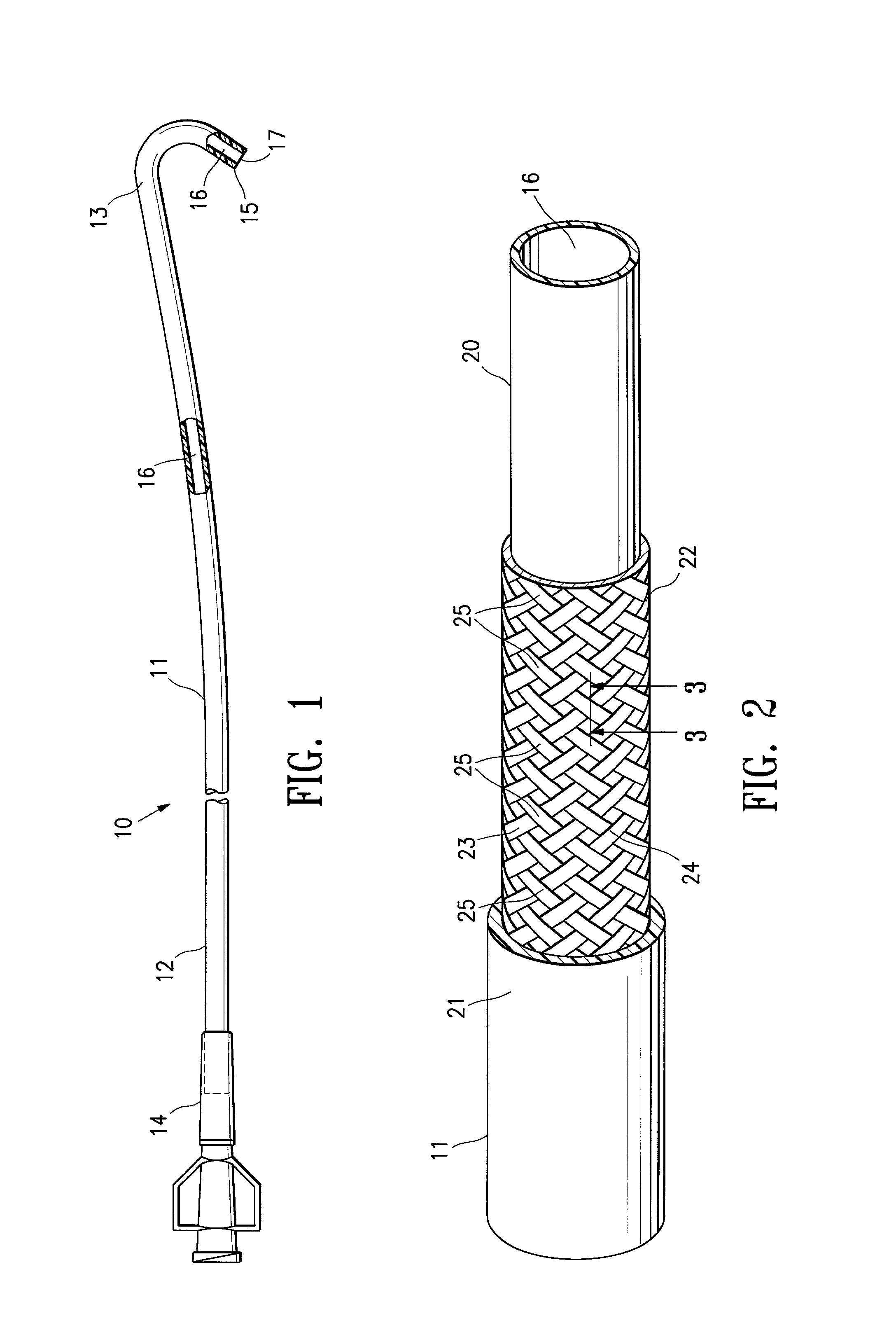
[0026] FIG. 1 illustrates a catheter 10 embodying features of the invention which generally includes an elongated catheter shaft 11 with a proximal shaft section 12 and a shaped distal shaft section 13, an adapter 14 mounted on the proximal end of proximal shaft section 12, a non-traumatic distal tip 15 and an inner lumen 16 which extends within the catheter shaft 11 from the proximal end thereof to a port 17 located in the distal end of the shaft.

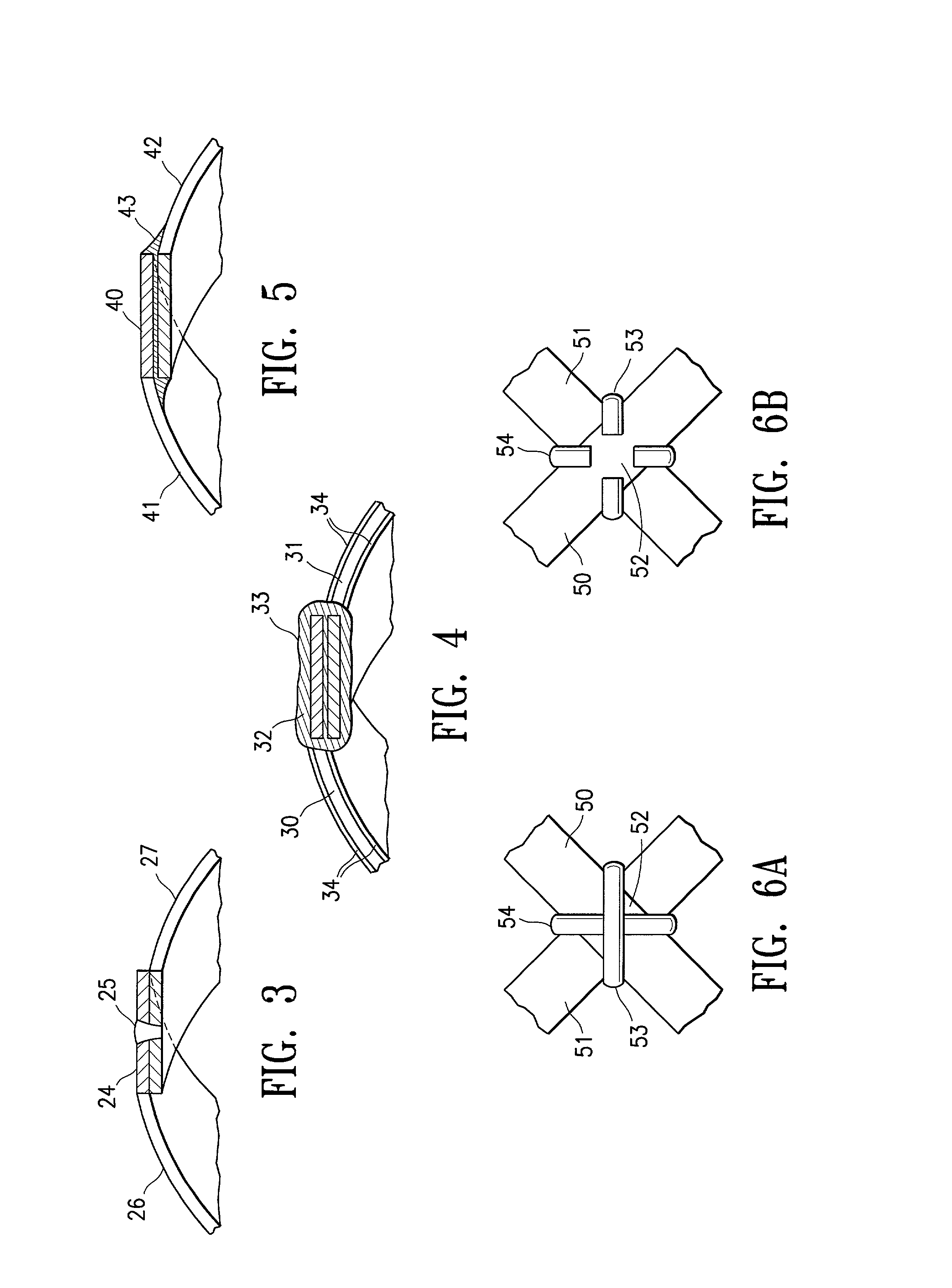
[0027] As shown in greater detail in FIG. 2, the elongated catheter shaft 11 is formed of inner polymeric layer 20, an outer polymeric layer 21 and a braided reinforcing structure 22 formed of multiple strands 23 disposed between the inner and outer polymeric layers. At multiple cross point locations 24 where two strands cross over, the strands are bonded or secured together by welding with the weldment being designated by reference number 25. The strands at every cross point need not be secured; however, the more cross points that are sec...


PUM


Abstract

An intracorporeal catheter such as a guiding catheter employed for intravascular procedures which generally has an elongated catheter shaft with a polymeric wall with a multistrand reinforcing structure wherein the strands at a plurality of cross point locations of the reinforcing structure are secured together to hold at least part of the braided reinforcing structure in a desired shape for utilization. The strands may be metallic or polymeric or mixtures thereof. The strands can be secured together at the cross points thereof by a variety of ways. In one embodiment a plurality of the strands forming the reinforcing structure are formed of metal and are provided with a coating of solder so that the strands can be secured together by applying heat to the strands at the cross point locations to melt the solder and allow a solidified solder connection between the strands to be formed upon cooling while holding at least the portion of the reinforcing structure having secured cross points while holding the portion of the reinforcing structure in the desire shape. Other embodiment involve other methods of securing the strands at the cross points including welding, brazing, adhesives or mechanical connections.

Description

FIELD OF INVENTION[0001] The invention relates to the field of intraluminal catheters, and particularly to guiding catheters suitable for intravascular procedures such as angioplasty, stent deployment and the like.BACKGROUND OF THE INVENTION[0002] In percutaneous transluminal coronary angioplasty (PTCA) procedures a guiding catheter having a shaped distal section is percutaneously introduced into the patient's vasculature by a conventional "Seldinger" technique and then advanced through the patient's vasculature until the shaped distal section of the guiding catheter is adjacent to the ostium of a desired coronary artery. The proximal end of the guiding catheter, which extends out of the patient, is torqued to rotate the shaped distal section and, as the distal section rotates, it is guided into desired coronary ostium. The distal section of the guiding catheter is shaped so as to engage a surface of the ascending aorta and thereby seat the distal end of the guiding catheter in the ...

Claims


Application Information

Patent Timeline
IPC IPC(8): A61M25/00
CPCA61M25/005
Inventor HOSTE, JOHN H.GRAHAM, HOWARDWROLSTAD, DAVID K.WILSON, BRUCE
Owner ABBOTT CARDIOVASCULAR
Why Eureka
Eureka Blog
Learn More