Circuit breaker, and accessory switches thereof

a circuit breaker and accessory switch technology, applied in the direction of circuit breaker switches, protective switch details, protective switch operating/release mechanisms, etc., can solve problems such as difficulty in ensuring smooth operation

Inactive Publication Date: 2002-06-27
FUJI ELECTRIC FA COMPONENTS & SYST CO LTD
View PDF0 Cites 17 Cited by
  • Summary
  • Abstract
  • Description
  • Claims
  • Application Information

AI Technical Summary

Problems solved by technology

(1) The pair of output protrusions 6a are formed in non-symmetrical positions on the open-close lever 6 so as to match the positions of operation levers of the ancillary switches 7 provided in the accessory switch housing sections 1a and 1b. For this reason, as shown in FIG. 8B, the output protrusion 6a assumes a complicated stepped geometry.
(2) The alarm output plate 8 is provided along the exterior of the frame of the open-close mechanism section 3 and effects guiding and supporting action in a vertically slidable manner without involvement of occurrence of interference with the open-close lever 6. By means of the a toggle shaft and a drive spring of the open-close mechanism which causes pivotal movement at the time of tipping operation, the alarm output plate 8 is actuated. Therefore, the alarm output plate 8 assumes a complicated geometry and a complicated guide mechanism. Hence, the number of parts constituting the alarm output plate 8, the number of processes for assembling the alarm output plate 8, and the space occupied by the alarm output plate 8 become large. In terms of operation, friction or abrasion of components of the guide mechanism stemming from sliding action is apt to cause resistance or rattle, thus posing difficulty in ensuring smooth operation over a long period of time.

Method used


Image

  • Circuit breaker, and accessory switches thereof
  • Circuit breaker, and accessory switches thereof
  • Circuit breaker, and accessory switches thereof

Examples


Embodiment Construction

]

[0035] An embodiment of the present invention will be described hereinbelow by reference to FIGS. 1 through 6B. In the drawings, those members which are the same as those shown in FIGS. 7 and 8 are assigned the same reference numerals, and their detailed explanations thereof are omitted.

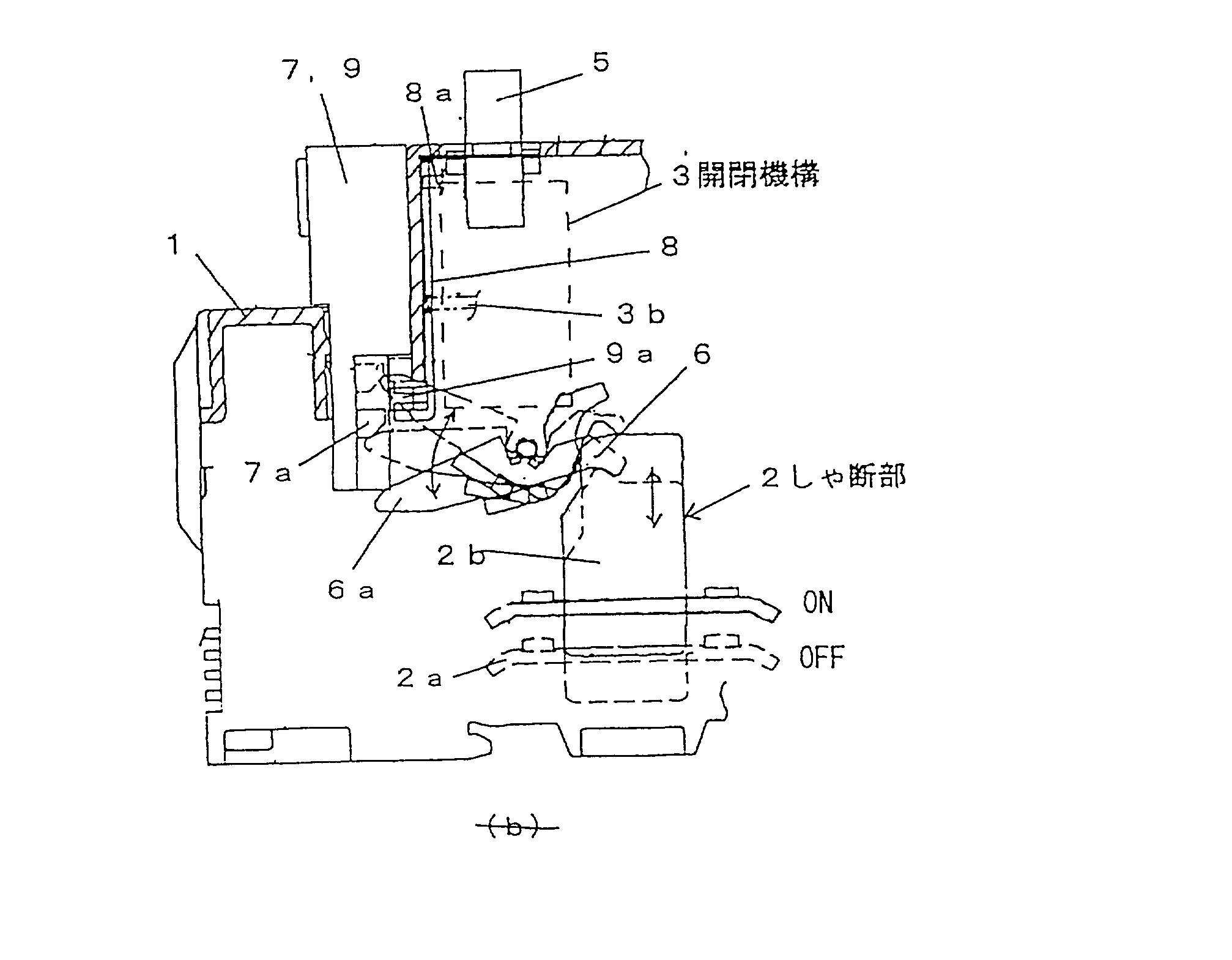
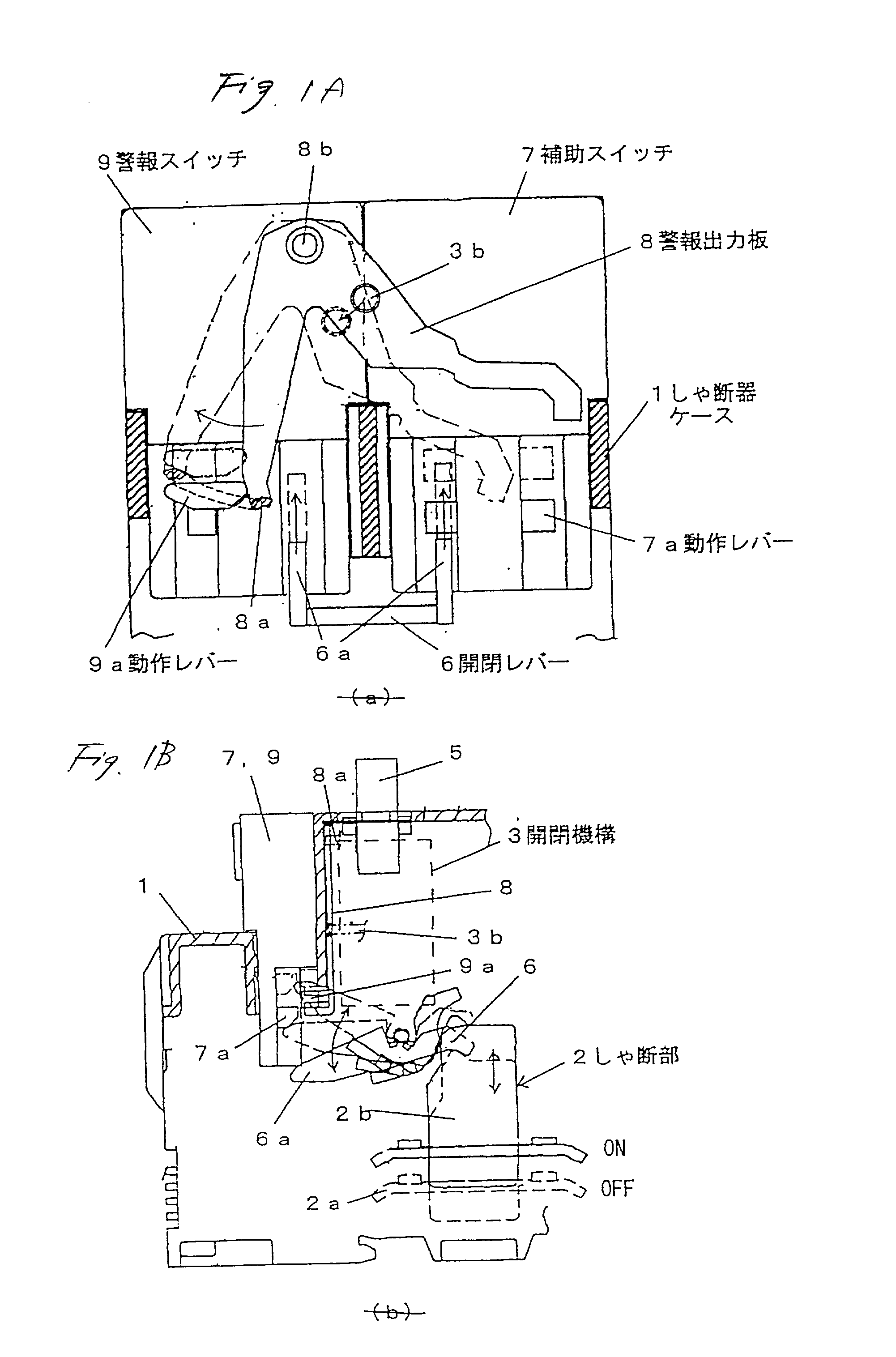
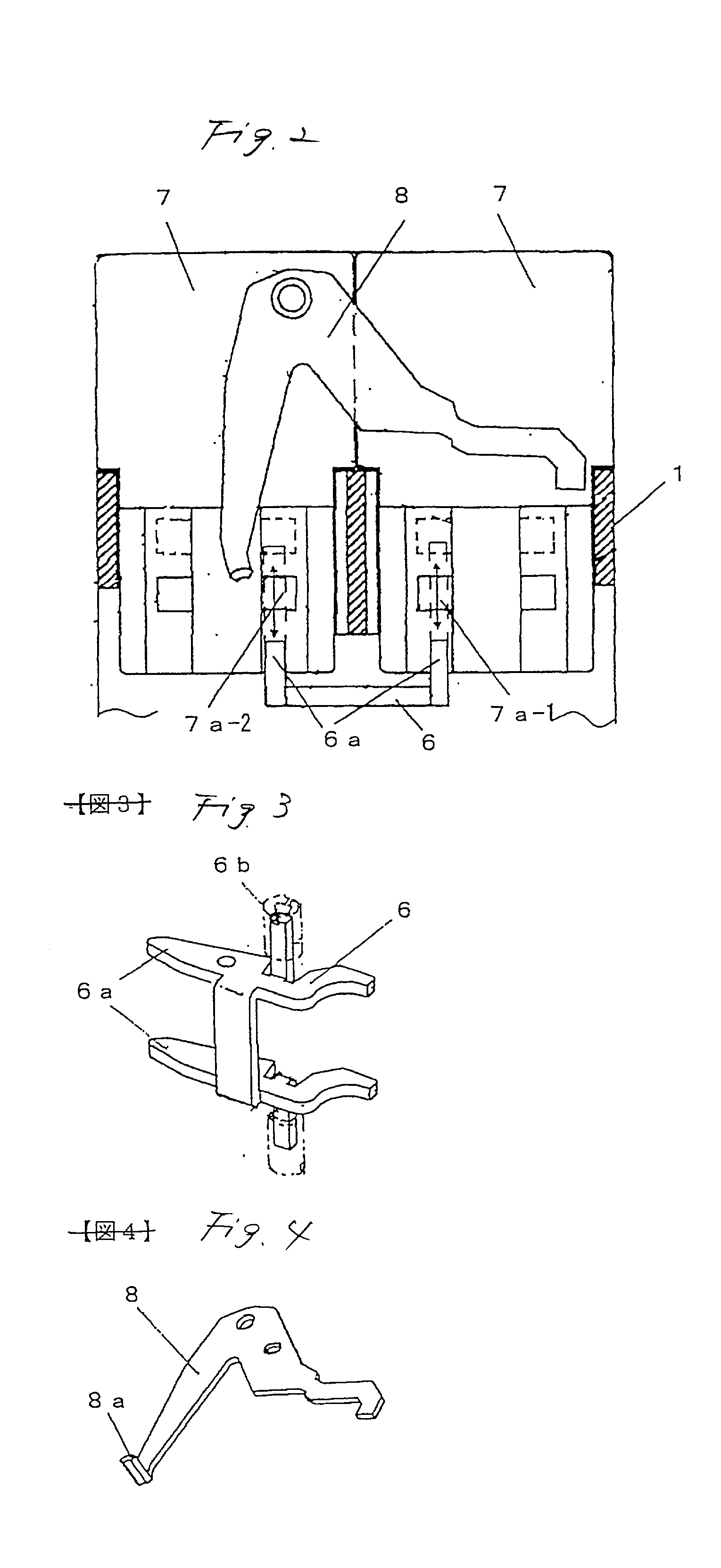
[0036] In the illustrated embodiment, as shown in FIG. 3, an open-close lever 6 is bifurcated into two output protrusions 6a in a symmetrical pattern. In a state in which the open-close lever 6 is attached to a breaker main unit, the output protrusions 6a are arranged in a symmetrical pattern with respect to a pair of accessory switch housing sections formed on the breaker case 1, as shown in FIGS. 1A and 2. The output protrusions 6a protrude downward toward the respective accessory switch housing sections.

[0037] As shown in FIG. 4, the alarm output plate 8 assumes the shape of a reverse V-shaped pivotal lever. The alarm output plate 8 is placed in an upper position relative to the output protrusion...


PUM


Abstract

In relation to a circuit breaker, a left-side accessory switch storage section and a right-side accessory switch storage section are provided in a breaker case 1. A contact point of an ancillary switch 7 provided in one of the accessory switch storage sections is opened or closed in conjunction with an output protrusion 6a formed on an open-close lever 6 of an open-close mechanism section 3 on the main unit. A contact point of an alarm switch 9 provided in the remaining accessory switch storage section is opened or closed in conjunction with an alarm output plate 8 which operates in association with tipping action of the breaker. The output protrusion 6a is caused to oppose an operation lever 7a of an ancillary switch which is formed into a symmetrical bifurcated shape and which is provided in the accessory switch storage section. The alarm output plate constitutes a pivotal lever coupled to a toggle shaft 3a of the open-close mechanism section. An output protrusion 8a provided at the extremity of the pivotal lever is caused to oppose an operation lever 9a of the alarm switch provided in the accessory switch storage section.

Description

[0001] 1. Technical Field[0002] The present invention is intended for a molded case circuit breaker for protecting a low-tension power distribution facility, such as an electric motor, from an overcurrent. The present invention relates to interior accessories (e.g., optional components), such as an ancillary switch for detecting the ON / OFF status of a primary circuit contact point and a tripping action, a circuit breaker equipped with an alarm switch, and their accessory switches.[0003] 2. Related Art[0004] FIG. 7 shows the configuration of a related-art example of molded case circuit breaker equipped with an ancillary switch and an alarm switch (i.e., interior accessory switches).[0005] As shown in FIG. 7, reference numeral 1 designates a case (plastic mold case) of a circuit breaker. The case 1 houses a breaking section 2 of a main circuit, a toggle-link-type open-close mechanism section 3, and a tipping section 4. The open-close mechanism section 3 is coupled to an assembly (not ...

Claims


Application Information

Patent Timeline
Patent Type & Authority Applications(United States)
IPC IPC(8): H01H71/04H01H71/46H01H71/50H01H73/02
CPCH01H71/04H01H71/501H01H71/465
Inventor YAMAGATA, HIDETOUCHIDA, NAOSHIASAKAWA, KOJITOYAMA, KENTARONOMURA, KOJI
Owner FUJI ELECTRIC FA COMPONENTS & SYST CO LTD
Why Eureka
Try Eureka