Mixer, radar module, and communication apparatus incorporating the same

a radar module and mixer technology, applied in the direction of instruments, waveguides, computations using denominational number representations, etc., can solve the problems of high frequency energy leakage from the filter circuit, signal does not necessarily produce resonance, and loss of entire losses

Inactive Publication Date: 2002-07-04
MURATA MFG CO LTD
View PDF0 Cites 6 Cited by
  • Summary
  • Abstract
  • Description
  • Claims
  • Application Information

AI Technical Summary

Benefits of technology

[0011] In addition, the mixer according to one of the first and second aspects may further include electrode separating portions formed to separate the electrodes to which both terminals of at least one of the diodes are connected, so that a direct current does not flow through the electrodes. With this arrangement, since a bias voltage can be applied to the at least one of the diodes from an external power source and thereby the diode can be driven at an optimum driving point, loss in the mixer can be reduced.
[0012] In addition, each of the electrode separating portions may be formed at a position where the intensity of an electric field is high in the planar TE-mode dielectric resonator. With this arrangement, the effect of reducing conductive loss can be enhanced.
[0013] In addition, the electrode apertures may be rectangular-shaped, and therefore the dielectric resonator may be a rectangular planar TE-mode dielectric resonator. With this arrangement, the formation of electrode patterns can be facilitated. Furthermore, a dielectric resonator having a high Q, which is capable of suppressing the occurrence of a spurious mode, can be formed on the dielectric substrate having a limited area.
[0014] In addition, the mixer of the invention may further include a dielectric strip arranged between the two conductive plates to form a dielectric line, which is coupled with the TE-mode dielectric resonator and is used as a signal-input line. This arrangement enables the easy formation of a mixer incorporated in an apparatus using a dielectric line as a transmission line.
[0015] According to a third aspect of the invention, there is provided a radar module including the mixer of the invention. The mixer is disposed in a circuit section mixing a received signal with a local signal. With this arrangement, the radar module can obtain high efficiency to improve detection capabilities.
[0016] According to a fourth aspect of the invention, there is provided a communication apparatus including the mixer of the invention. The mixer is disposed in a circuit section mixing one of a received signal and a transmitted signal with a local signal. With this arrangement, while reducing loss, frequency conversion can be performed to obtain high sensitivity.

Problems solved by technology

However, between the filter circuits composed of stubs of the suspended lines, a signal does not necessarily produce resonance.
Thus, high frequency energy leaks from the filter circuits composed of the stubs and the like.
In addition, due to the suspended lines having a low Q, the entire loss increases.

Method used


Image

  • Mixer, radar module, and communication apparatus incorporating the same
  • Mixer, radar module, and communication apparatus incorporating the same
  • Mixer, radar module, and communication apparatus incorporating the same

Examples


first embodiment

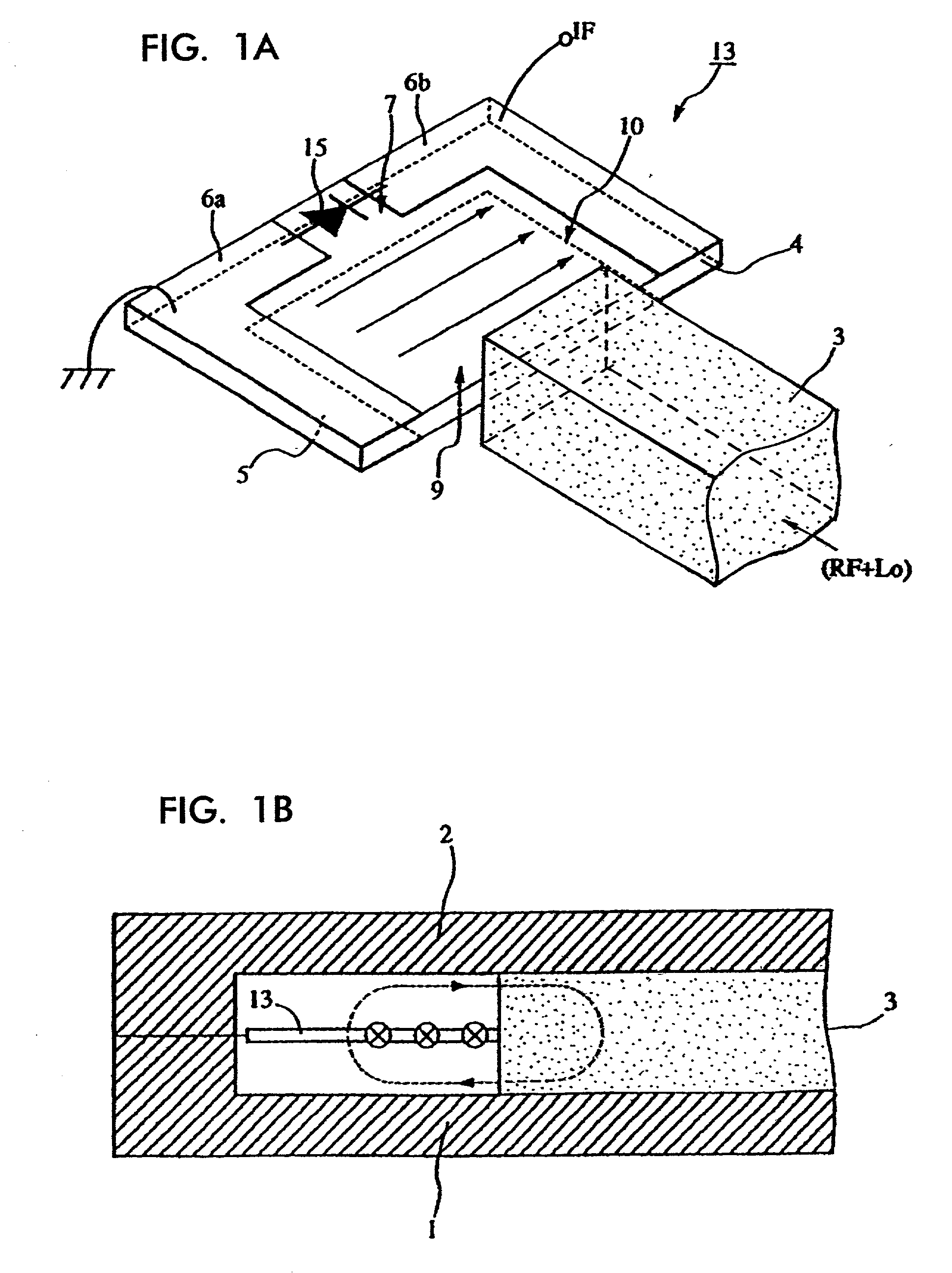
[0028] FIGS. 1A and 1B show the structure of a mixer according the present invention.

[0029] FIG. 1A is a perspective view of the main part of the mixer when upper and lower conductive plates are removed. FIG. 1B is a section of the main part thereof. In these figures, reference numeral 4 denotes a rectangular planar dielectric substrate. An electrode 5 is formed on the lower surface of the substrate 4 and electrodes 6a and 6b are formed on the upper surface thereof. The electrode 5 and the electrodes 6a and 6b are arranged such that electrode apertures 9 and 10 are opposed to each other via the dielectric substrate 4. The part of the dielectric substrate sandwiched between the mutually opposing electrode apertures 9 and 10 serves as a rectangular planar TE-mode dielectric resonator.

[0030] In addition, a slit 7 continuous with the electrode aperture 10 is formed on the upper surface of the dielectric substrate 4. A mixer diode 15 such as a Schottky barrier diode is connected in a man...

third embodiment

[0054] Referring to FIG. 7, a description will be given of a mixer according to the invention.

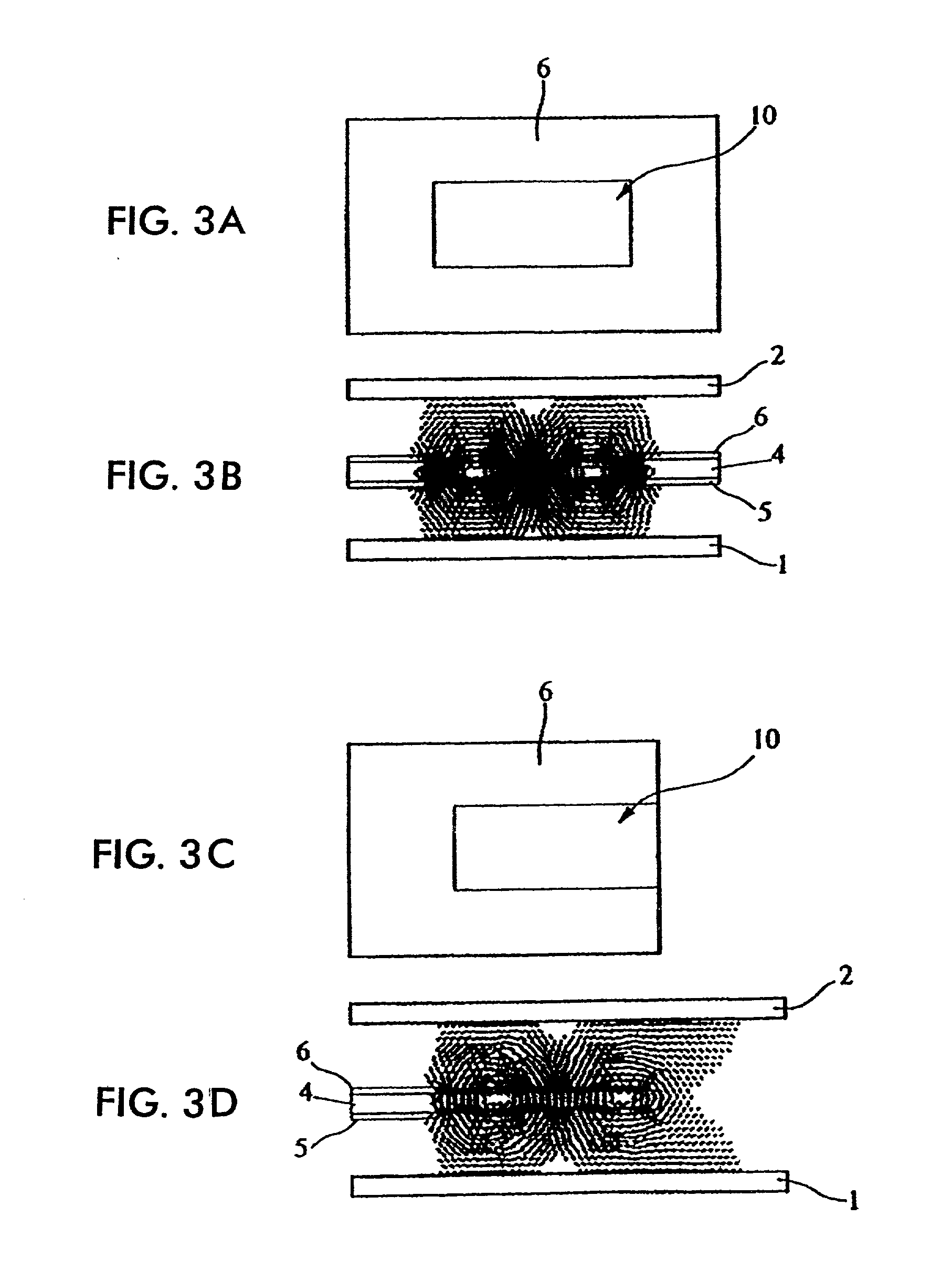
[0055] FIG. 7 also shows a part corresponding to the part shown in FIG. 1A in the first embodiment. Each of the first and second embodiments uses the rectangular planar TE-mode dielectric resonator in which one end of each electrode is open-circuited and the open-circuited electrode portions of the dielectric resonator are positioned near the end of the dielectric strip 3. However, the embodiment shown in FIG. 7 uses the rectangular planar TE-mode dielectric resonator in which both ends of the electrodes are short-circuited, as shown in FIGS. 3A and 3B. With the use of the resonator having the electrodes with both ends short-circuited, as compared with the resonator having the electrodes with one end open-circuited, a mixer having a higher unloaded Q and lower loss can be formed. However, since the strength of coupling between the dielectric resonator and the dielectric line reduces, the mi...

fourth embodiment

[0059] Referring to FIG. 8, a description will be given of a mixer according to the invention.

[0060] Although each of the first to third embodiments uses the dielectric line as a signal-input line, the mixer shown in FIG. 8 uses a waveguide as a signal-input line. Specifically, in FIG. 8, reference numeral 14 denotes a rectangular waveguide. The circuit board 13 shown in one of FIGS. 1, 6, and 7 is arranged inside the rectangular waveguide. In this arrangement, the electromagnetic field of a TE10 mode wave propagating through the waveguide couples with the electromagnetic field of a rectangular planar TE-mode dielectric resonator formed on the circuit board 13. The mixer of the fourth embodiment is easily suitable to an apparatus using a waveguide as a transmission line.


PUM


Abstract

A mixer used in a millimeter-wave band and a microwave band capable of achieving loss reduction, a radar module, and a communication apparatus incorporating the mixer and having high efficiency. The mixer includes two electrodes formed on one main surface of a dielectric substrate and another electrode formed on another main surface thereof such that non-electrode portions on both main surfaces are opposed to each other via the dielectric substrate. Additionally, a diode is connected bridging a slit between the two electrodes on one main surface to constitute a circuit board. The circuit board and a dielectric strip are arranged between upper and lower conductive plates.

Description

[0001] 1. Field of the Invention[0002] The present invention relates to mixers used in a millimeter wave band and a microwave band, radar modules, and communication apparatus incorporating the same.[0003] 2. Description of the Related Art[0004] As a conventional mixer, Japanese Unexamined Patent Application Publication No. 10-75109 describes a mixer having a structure in which a diode is mounted in a non-radiative dielectric line (NRD guide).[0005] In the above structure, a dielectric strip and a circuit board are arranged between two substantially parallel conductive plates to form a dielectric line. The conductive plates and conductive patterns on the circuit board constitute suspended lines. Additionally, the conductive patterns of the suspended lines are disposed in a direction crossing substantially perpendicularly to the dielectric strip, and also there are arranged filter circuits coupled with the dielectric line to block signals propagating through the suspended lines at at ...

Claims


Application Information

Patent Timeline
Patent Type & Authority Applications(United States)
IPC IPC(8): H01P3/08H01P7/10H01P3/16H01P5/08H03D9/06
CPCH03D9/0633H01P3/08
Inventor IWATANI, HIDETOSHIYAMASHITA, SADAO
Owner MURATA MFG CO LTD
Why Eureka
Try Eureka