Powder spray coating system

a spray system and spray technology, applied in the direction of electric spraying apparatus, burners, liquid supply arrangements, etc., can solve the problems of contaminating the entire hopper, increasing the cost and space required to maintain such equipment, and changing the hopper can take several minutes, so as to quickly and easily isolate the hopper, quickly remove the connection, and quickly purged

Inactive Publication Date: 2002-08-15
MILLERKNOLL INC
View PDF0 Cites 3 Cited by
  • Summary
  • Abstract
  • Description
  • Claims
  • Application Information

AI Technical Summary

Benefits of technology

0011] The present inventions provide significant advantages over other powder coating systems and methods for applying powder coating. For example, the system provides for a plurality of supply hoppers to be operably connected to a manifold. As such, individual hoppers do not have to be disconnected and removed after each color change cycle. Rather, one or more valves, preferably two, can be quickly and easily turned to isolate any particular hopper. In addition, the spray gun can be quickly removed from its connection with any one hopper. The spray gun, and any line extending therefrom, can be quickly purged between color changes so as to avoid contaminating either the next product to be sprayed and/or the supply hoppers. The spray gun can then be operably reconnected t

Problems solved by technology

Even with skilled operators, such changes can take several minutes.
However, many manufacturers run ten or more colors, which can thereby prohibitively increase the expense and space required to maintain such equipment.
Such systems, however, require the powder supply line to be disconnected from the gun and back purged to the supply hopper.
However, if residue from a different c

Method used


Image

  • Powder spray coating system
  • Powder spray coating system
  • Powder spray coating system

Examples


Embodiment Construction

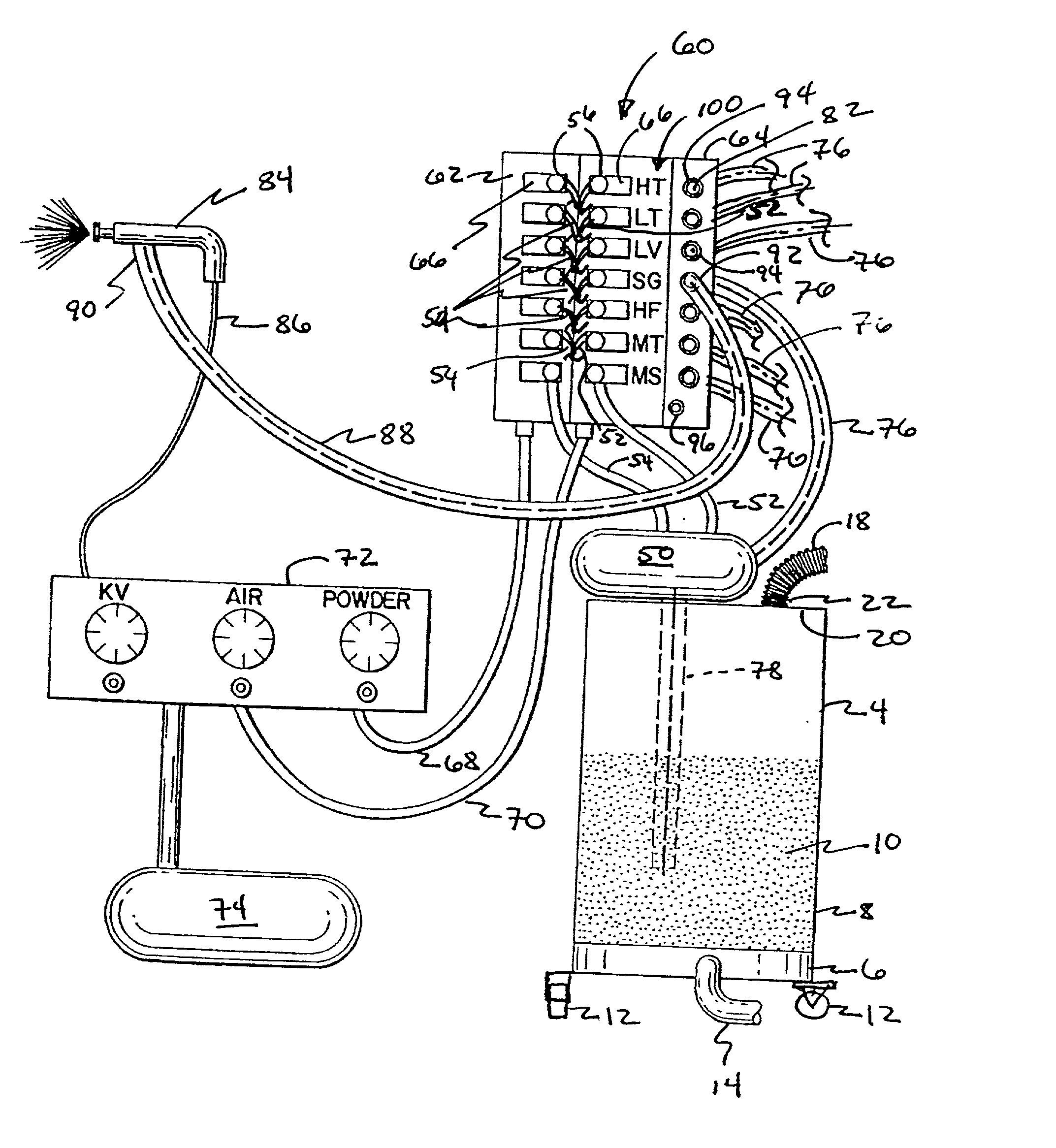
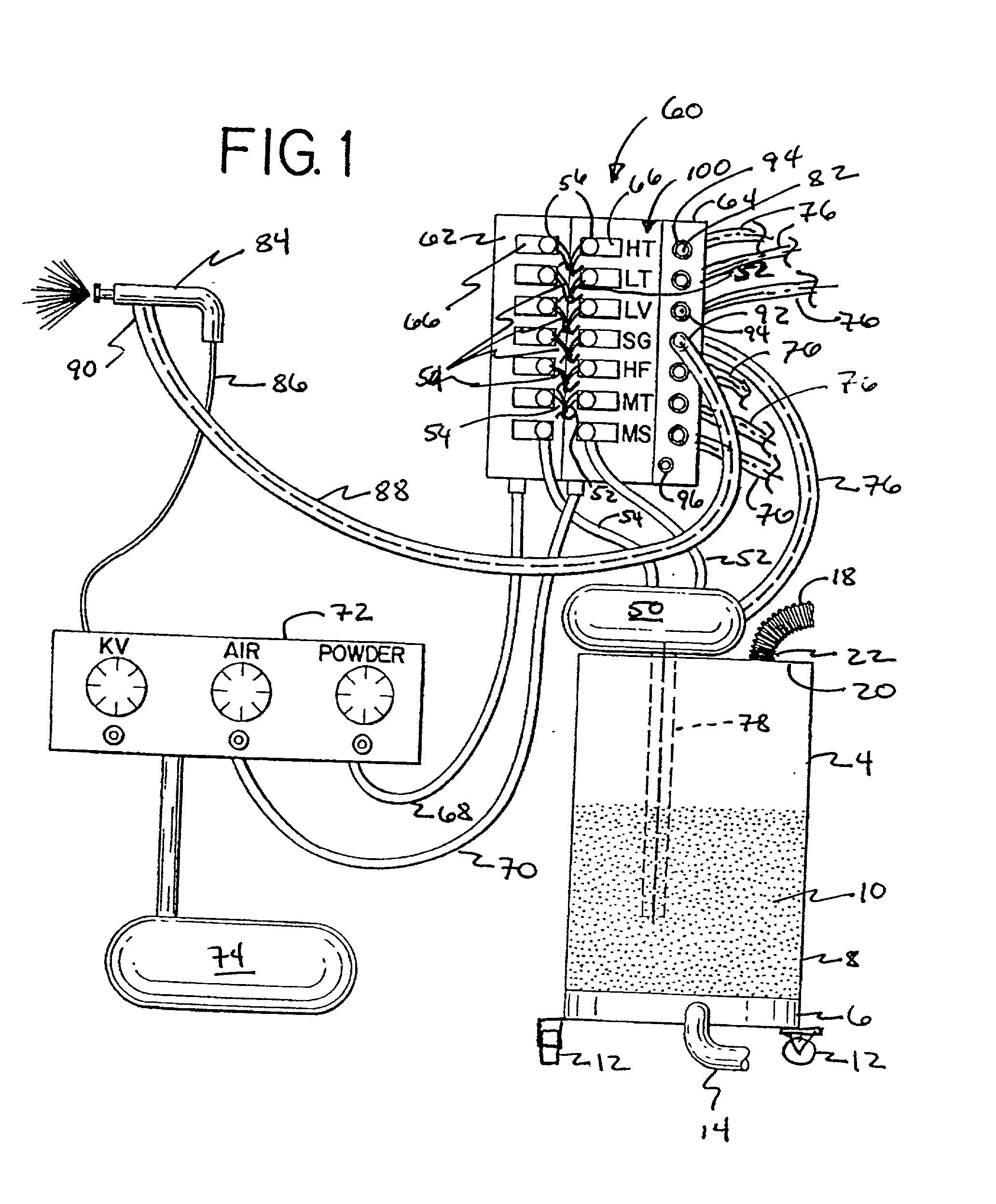
[0019] Referring to FIG. 1, a powder coating spray system 2 includes a powder supply hopper 4 having an upper portion 8 defining an interior space, at least a portion of which is filled with a powder 10, and a lower portion 6. The supply hopper 4, including the upper and lower portions, is preferably cylindrical and is preferably supported by a plurality of wheels that allow for the supply hopper to be portable and easily moveable from one location to the next. The hopper can be filled through a hatch 21 formed in an upper wall 20 of the hopper, or the entire upper wall, which is releasably attached to the upper portion with clamps, can be removed from the hopper to facilitate the cleaning thereof. Although only one supply hopper 4 is illustrated in FIG. 1 for the sake of simplicity, it should be understood that in the preferred embodiment, a plurality of supply hoppers are incorporated into the system, as shown for example in FIG. 3 and as further explained herein below. A fluidizi...


PUM


Abstract

A powder spray system comprises a plurality of supply hoppers, a purge air supply, a manifold operably connected to each of the plurality of supply hoppers, and a spray gun. The manifold comprises a plurality of outlets. The spray gun is operable in a plurality of spraying configurations and a purging configuration. The spray gun is selectively, removably connected to at least one of the outlets when in one of the plurality of the spraying configurations and is removably connected to the purge air supply when in the purging configuration. A method of operating a powder spray system also is provided.

Description

[0001] This application claims the benefit of U.S. Provisional Application Serial No. 60 / 260,997, filed Jan. 11, 2001, the entire disclosure of which is hereby incorporated by reference.[0002] The present invention relates generally to a powder spray coating system, and in particular, to a quick-change powder spray coating system.[0003] Powder spray coating systems are commonly used to powder coat various consumer products, typically metal, wood or plastic, such as office furniture, including for example storage units, and other general industrial powder coat applications, including for example, various automotive products and the like. In order to maintain smaller inventories while at the same time providing a wide selection of colors to the end user, it often is necessary and desirable to change the color being applied to one or more products several, dozens or even hundreds of times during a typical eight-hour shift. Typically, a hopper is used to supply the powder to one or more...

Claims


Application Information

Patent Timeline
IPC IPC(8): B05B5/16B05B7/14B05B12/14
CPCB05B5/1683B05B7/1404B05B7/1472B05B12/14B05B12/149
Inventor VOLLMER, DAVID J.
Owner MILLERKNOLL INC
Why Eureka
Try Eureka