Multi-band coax extender for in-building digital communication systems

a coax extender and digital communication technology, applied in the field of data communication, can solve the problems of service degradation, insufficient capacity, and the need to provide more expensive client modems, and achieve the effect of increasing data capacity

Inactive Publication Date: 2002-08-22
COAXMEDIA
View PDF25 Cites 74 Cited by
  • Summary
  • Abstract
  • Description
  • Claims
  • Application Information

AI Technical Summary

Benefits of technology

0027] The present invention solves the prior art limitations by utilizing a two-stage system. In the preferred embodiment, the feeder cable stage takes advantage of the capacity of the feeder cable to carry multiple bands of data in the frequency spectrum above 1 GHz. The local stage converts these bands of data into corresponding bands in the frequency range 900 MHz to 1 GHz, at the TV "booster" amplifier locations, and amplifies these downstream communications for onward transmission to end users connected in groups to individual local tree and branch networks in the TV coax distribution system. Likewise, at least some of the upstream communications are shifte

Problems solved by technology

Thus, in addition of the cost to upgrade the components of the legacy coax network, there would be a need to provide more expensive client modems that can operate on multiple downstream frequencies.
When too many users share the data distribution system, there may be insufficient capacity.
Insufficient capacity can lead to service degradation in the form of lost or delayed data packets.
Low latency applications such as video conferencing or voice over IP (Internet Protocol) exacerbate the problem.
While it may seem attractive to simply use additional frequencies for the upstream and or the downstream channel, this is not an attractive solution.
Even if a designer was willing to forego the advantages of using the same pair of transmit and receive frequencies for an entire set of client modems, there are practical limits to the number of frequency bands available above 900 MHz.
One problem is that approximately 1 GHz

Method used


Image

  • Multi-band coax extender for in-building digital communication systems
  • Multi-band coax extender for in-building digital communication systems
  • Multi-band coax extender for in-building digital communication systems

Examples


Embodiment Construction

[0034] Overview of FIGS. 4 and 5

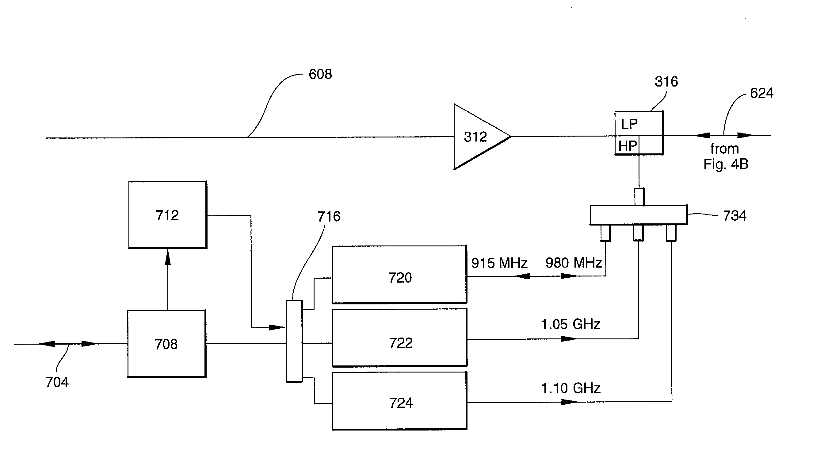
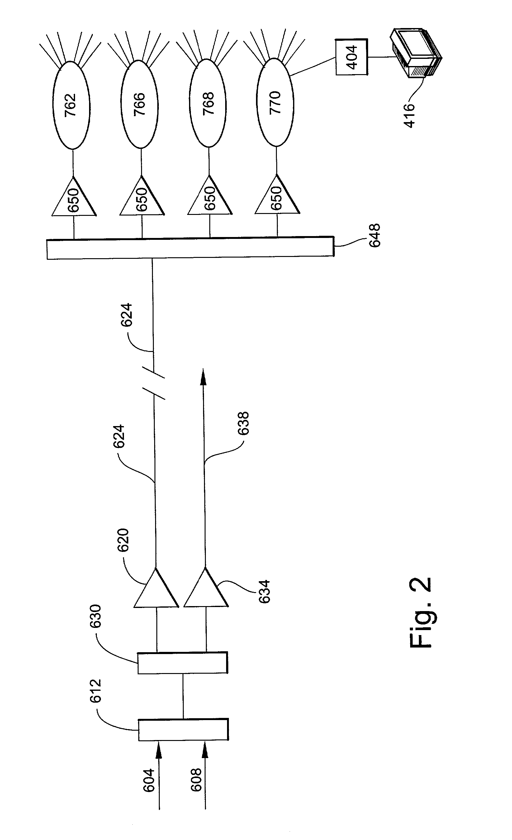
[0035] FIGS. 4 and 5 show two principal embodiments of the present invention. Both embodiments are shown on a combination of a Figure A that shows the equipment upstream of the feeder cable 624 and a Figure B that shows the equipment downstream of the feeder cable 624.

[0036] Both embodiments have one central system to feed one or more feeder cables (624 or 638) and ultimately a number of local networks. In the preferred embodiment, each local network would use standard client modems with pre-set frequencies for transmit and receive.

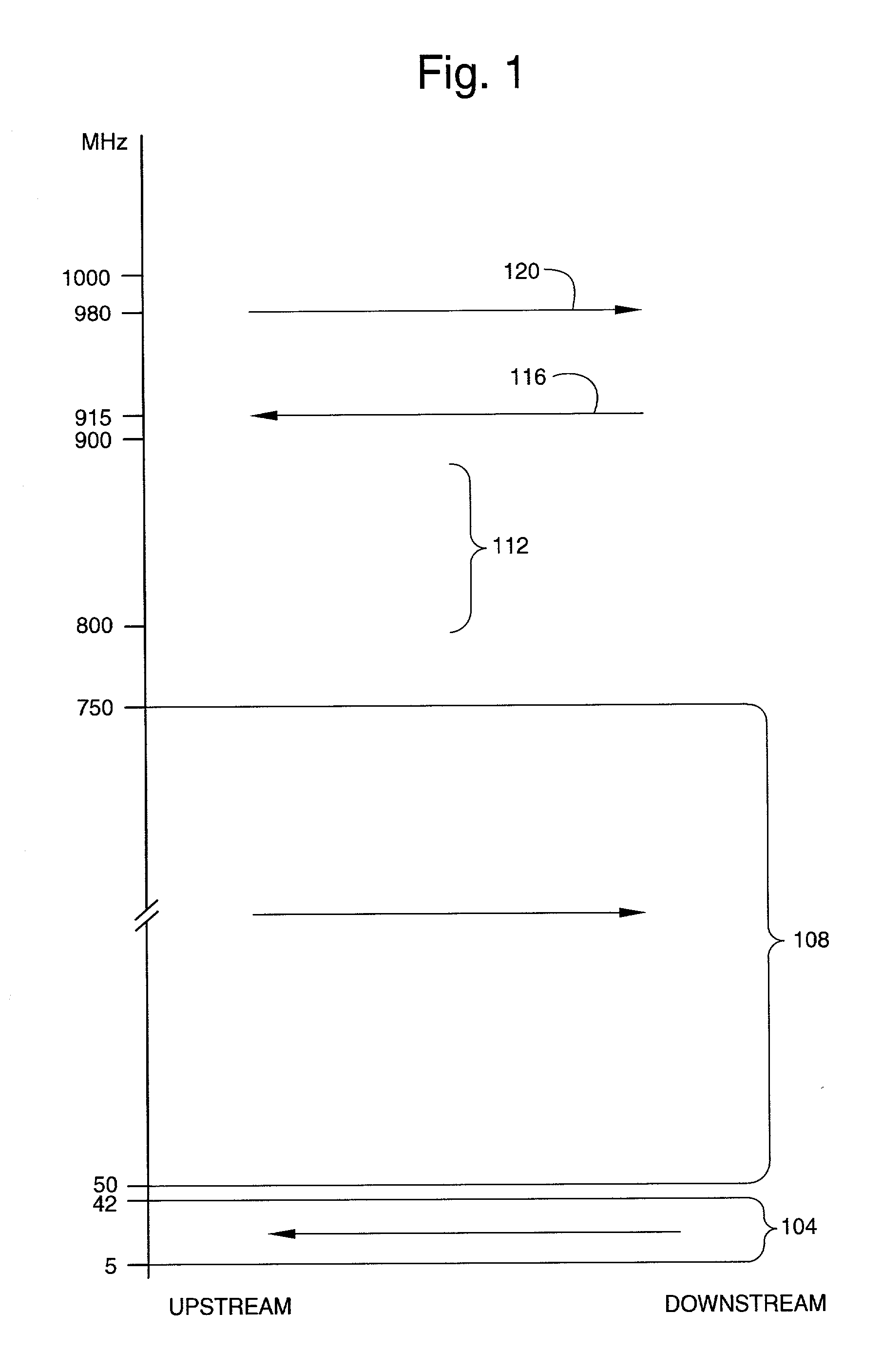
[0037] FIG. 4 differs from FIG. 5 in that FIG. 4 anticipates a situation where one upstream frequency is adequate for the entire set of client modems but the downstream data requirements exceed the bandwidth of a single downstream frequency. In both FIG. 4 and FIG. 5, the system uses several frequencies to carry downstream transmissions on the feeder cable before conversion to the standard downstream frequency for transmiss...


PUM


Abstract

A method and system to expand digital transmission capacity in a "tree and branch" coax distribution system employing distributed TV signal amplifiers. Specifically, a number of separate bands are used in a main feeder cable that are frequency shifted and applied to a number of local coax distribution networks. In the preferred embodiment each of the local coax distribution networks use the same pair of upstream and downstream frequencies. Using identical pairs of upstream and downstream frequencies allows the use of a single standardized non-tuning end-user data interface (client modem), that can be connected to any of the local coax distribution networks. This abstract is provided as a tool for those searching for patents, and not as a limitation on the scope of the claims.

Description

[0001] This application claims priority to a provisional application filed Feb. 7, 2001 with U.S. Serial No. 60 / 267,046. This application provides a way to boost the signal carrying capacity of a system to provide High Speed Data Communication Over Local Coaxial Cable as described in co-pending application Ser. No. 09 / 482,836 based on Provisional Application No. 60 / 115,646 filed Jan. 13, 1999. This application claims priority to the '836 application and also claims priority to another application assigned to common assignee coaXmedia, Inc and its priority document. The title of the claimed application is Architecture and Method for Automated Distributed Gain Control for Internet Communications for MDUs and Hotels (application Ser. No. 09 / 818,378 based on Provisional Application No. 60 / 193,855). The '855 application has the filing date of Mar. 30, 2000.[0002] For the convenience of the reader, applicant has added a number of topic headings to make the internal organization of this sp...

Claims


Application Information

Patent Timeline
IPC IPC(8): H04L1/00H04L1/16H04L12/28H04N7/10H04N7/173H04Q11/04
CPCH04L12/2801H04L12/2856H04L12/2872H04N7/10H04N7/106H04Q11/0478
Inventor TERRY, JOHN B.JACKSON, HAROLD W.TERRY, DOROTHY
Owner COAXMEDIA
Why Eureka
Try Eureka