Vented compartment inerting system

a technology of inerting system and venting compartment, which is applied in the direction of liquid handling installation, separation of dispersed particles, and separation of separation processes, etc., can solve the problems of over 75 billion dollars in the world for altering the fuel flash point, unable to relocate the fuel tank, and only being able to fly on new airplanes

Inactive Publication Date: 2002-08-29
LAIR LIQUIDE SA POUR LETUDE & LEXPLOITATION DES PROCEDES GEORGES CLAUDE
View PDF0 Cites 13 Cited by
  • Summary
  • Abstract
  • Description
  • Claims
  • Application Information

AI Technical Summary

Problems solved by technology

However, relocation of the fuel tanks is only feasible on new airplanes; full-time ventilation of the fuel tanks is estimated to cost over 3.5 billion dollars over ten years, and alteration of the fuel flash point is estimated to cost over 75 billion dollars worldwide over ten years.
But merely blowing an inert gas into a vented fuel compartment is not a desirable or effective solution.
A problem that exists is that introduction of a volume of nitrogen into a vented fuel tank will necessarily cause venting of an equivalent volume of ullage from the compartment.
Even if this mixture is captured and safely handled, the removal of the displaced fuel vapors can add up to a large loss of valuable fuel and have a significant impact on the environment by the needless dumping of the hydrocarbon fuel into the atmosphere.

Method used


Image

  • Vented compartment inerting system
  • Vented compartment inerting system
  • Vented compartment inerting system

Examples


first embodiment

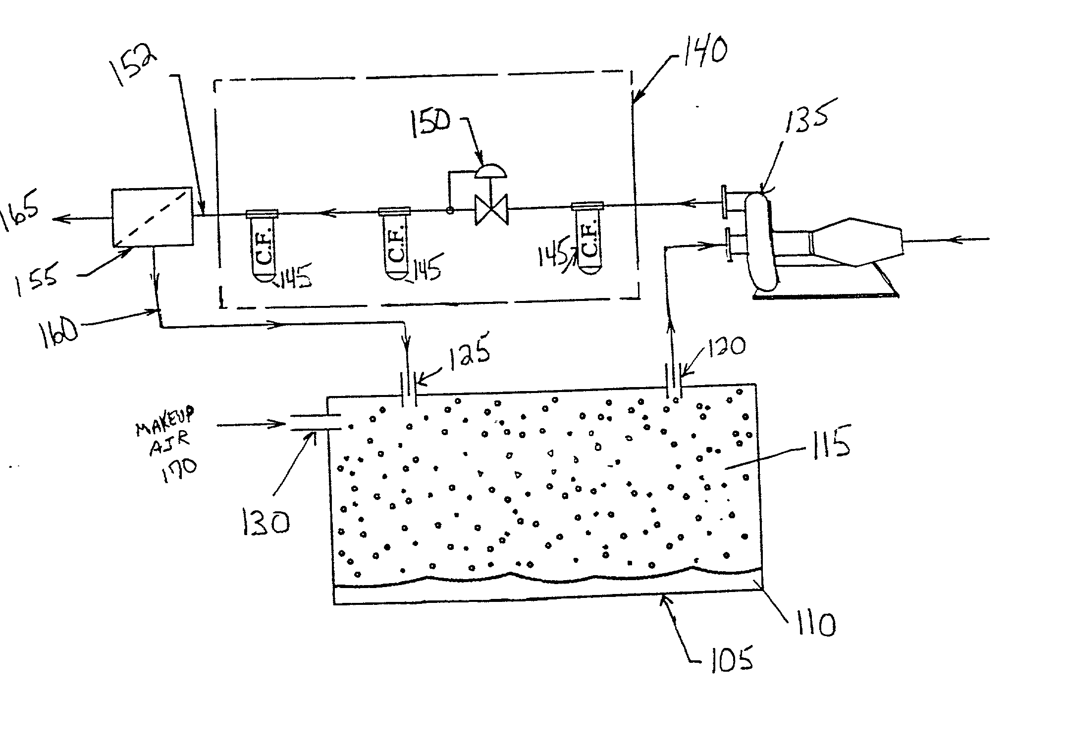
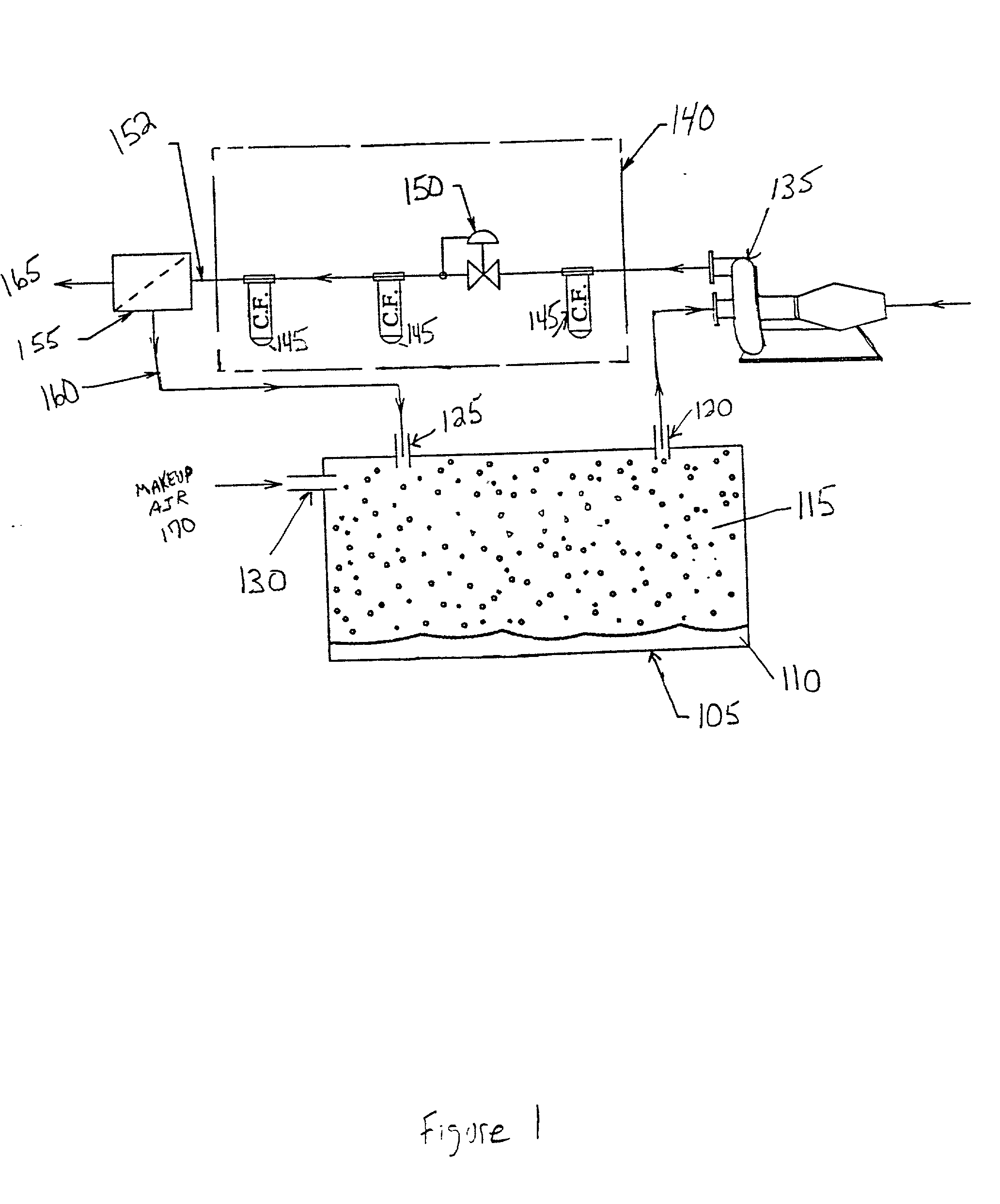
[0034] As in the first embodiment, ullage 115 from the tank 105 is routed to a turbine driven compressor 135, which compresses the ullage and passes it to conditioning equipment 140, including filters 145 and a pressure regulator 150, and optionally a heat exchanger. The conditioned stream 152 from the conditioning equipment 140 is fed to a first separator 155, from which the OEA stream 165 is exhausted and the NEA stream 160 is fed to the tank 105.

second embodiment

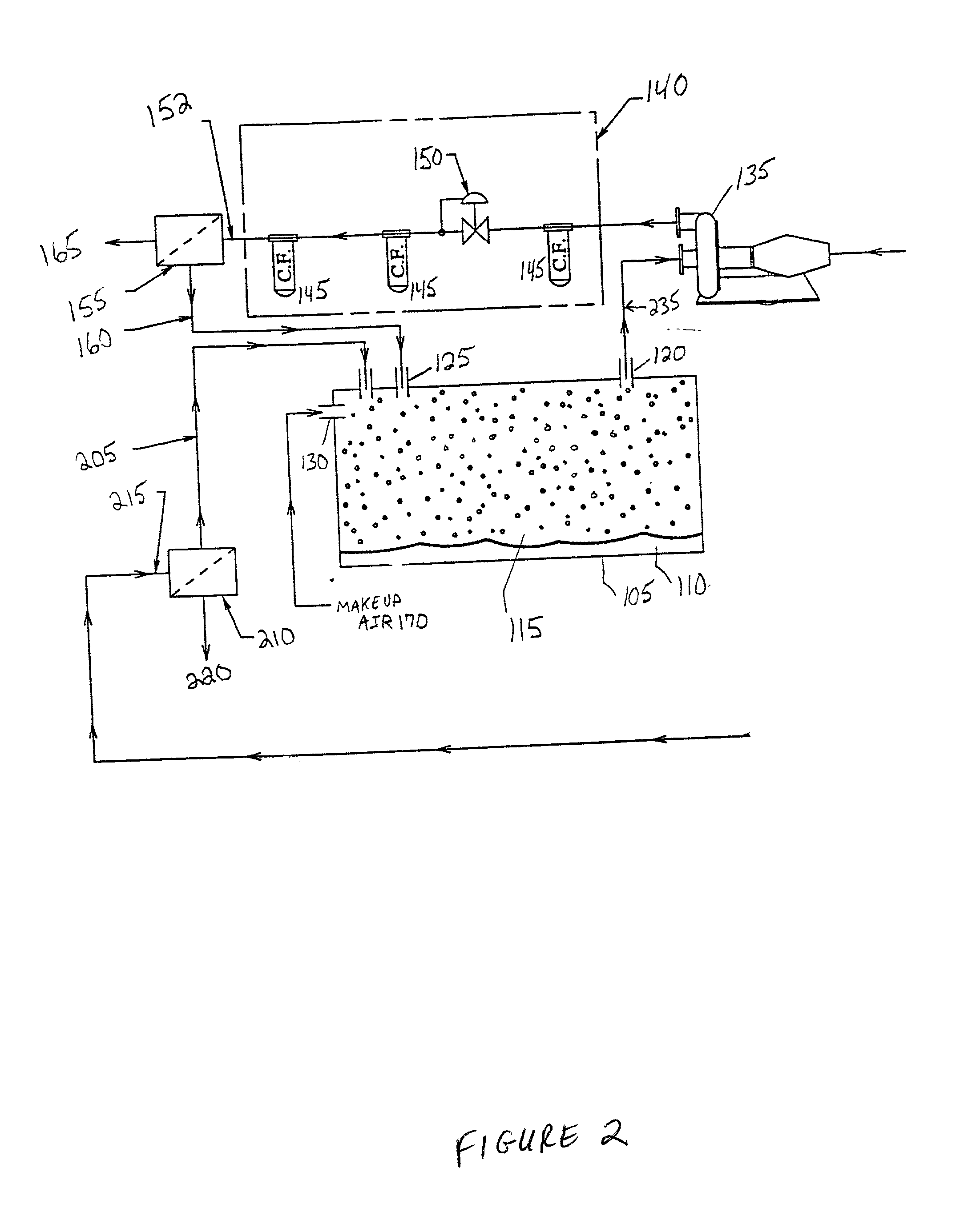
[0035] However, in this embodiment, a make up NEA stream 205 for the tank 105 that replaces the volume of OEA 165 from the first separator 155 comes from a second separator 210. Compressed air 215 is fed to this second separator 210, which separates the air into a second OEA stream 220 and a make up NEA stream 205. The OEA stream 220 is exhausted, while the make up NEA stream 205 is fed to the tank 105 in sufficient flow rate to replace the volume of gas lost to the OEA stream 165 from the first separator 155. In this way, the net volumetric flow from the tank 105 is zero, which precludes the need for any ambient make up air 170. Table 2 shows the relative flow rates, pressures, and temperatures of gas flows in this

[0036] Advantageously, because the O.sub.2 level in the make up NEA gas 205 is near zero, the inerting of the tank 105 can be accomplished in a significantly reduced time over an apparatus that uses only ambient make up air 170.

[0037] It should be noted that it is not nec...


PUM

PropertyMeasurementUnit
flammableaaaaaaaaaa
volumeaaaaaaaaaa
permeableaaaaaaaaaa

Abstract

1. An inerting system for a vented controlled atmosphere container, for inerting a flammable gas comprising a flammable vapor and oxygen, comprising: (i) a container; (ii) an outlet in the container for the flammable gas; (iii) a compressor, in fluid communication with the outlet, which compresses the flammable gas from the container; (iv) a separator, in fluid communication with the compressor, for removing oxygen from the flammable gas to produce an oxygen-depleted flammable gas; (v) an inlet in the container, which is in fluid communication with the separator; through which the oxygen-depleted flammable gas is fed into the container.

Description

[0001] 1. Field of the Invention[0002] The present invention relates to a vented compartment inerting device for quickly and selectively rendering a vented compartment nonexplosive and, more particularly, to a method and apparatus for rapid and efficient inerting of a vented compartment.[0003] 2. Description of the Related Art[0004] According to the Federal Aviation Administration, at least ten airplane loss events between 1959 and 1998 have involved fuel tank explosions. There is a thus a need in the aviation industry for eliminating, or reducing the risk due to explosive fuel-air mixtures in fuel tanks of airplanes. The U.S. Federal Aviation Administration has studied various potential solutions for reducing the risk of fuel tank explosions, including reducing the heat input to tanks by ventilation or relocation of the tanks, altering fuel properties such as raising the flash point, and fuel inerting. However, relocation of the fuel tanks is only feasible on new airplanes; full-ti...

Claims


Application Information

Patent Timeline
Patent Type & Authority Applications(United States)
IPC IPC(8): A62C3/06A62C3/08B64D37/32B64F1/28
CPCA62C3/06A62C3/08B64D37/32B64F1/28
Inventor BEERS, KARL S.
Owner LAIR LIQUIDE SA POUR LETUDE & LEXPLOITATION DES PROCEDES GEORGES CLAUDE
Why Eureka
Try Eureka