Fuel system and method

a fuel system and fuel technology, applied in chemical methods analysis, drying, lighting and heating apparatus, etc., can solve the problems of affecting the reliability of fuel system components, affecting the operation delay, and water is an unavoidable contaminant in fuel, so as to improve the accessibility, reduce the need for maintenance, and save installation costs and weight

Active Publication Date: 2014-12-09
AIRBUS OPERATIONS LTD
View PDF22 Cites 16 Cited by
  • Summary
  • Abstract
  • Description
  • Claims
  • Application Information

AI Technical Summary

Benefits of technology

[0008]The volume of gas above the liquid fuel within the fuel tank is known as the ullage. The invention is advantageous in that water in the vapour phase within the ullage, and also within the vent tank, is fed to the gas drying system and dry gas is returned to the ullage. The gas drying system forms a partially closed loop so as to maintain a low level of humidity within the ullage. The loop is necessarily partially open due to the vent tank duct, which is open to the ambient atmosphere for pressure equalisation. Ingress moist ambient air into the vent tank via the duct will be processed by the gas drying system before being fed to the ullage. Accordingly, the gas drying system beneficially processes the ullage gas as well as ingress air to maintain a low level of humidity within the ullage. Reducing the ullage humidity reduces the dissolved water content of fuel in the fuel tank by inhibiting condensation of water vapour onto surfaces in the fuel tank and promoting evaporation of dissolved water from the fuel into the ullage atmosphere by natural humidity equalization. The higher pressure within the ullage than in the vent tank is sufficient to ensure that when there is a pressure differential between the ullage and the ambient atmosphere, ingress air passing through the duct and into the vent tank is processed by the gas drying system and is not fed directly into the ullage. In this way, moist ingress air is dehumidified before entering the ullage. Maintaining the content of water in the fuel tank at a low level improves fuel system component reliability, reduces maintenance activities, and reduces microbiological contamination.
[0026]The ability to retro-fit the gas drying system, or the gas drying / inerting system, as appropriate, to an existing fuel system is of particular benefit. Use can be made of existing vent lines in the fuel system, saving installation costs and weight. The pump may be the only moving part in the gas drying system, meaning minimal maintenance requirements. Installing the gas drying system in the vent tank, rather than the fuel tank, improves accessibility. In addition, the fuel volume of the fuel tank is not compromised.

Problems solved by technology

Water is an unavoidable contaminant in fuel.
It can affect fuel system component reliability and lead to operational delays and increased maintenance activities.

Method used


Image

  • Fuel system and method
  • Fuel system and method
  • Fuel system and method

Examples


Embodiment Construction

)

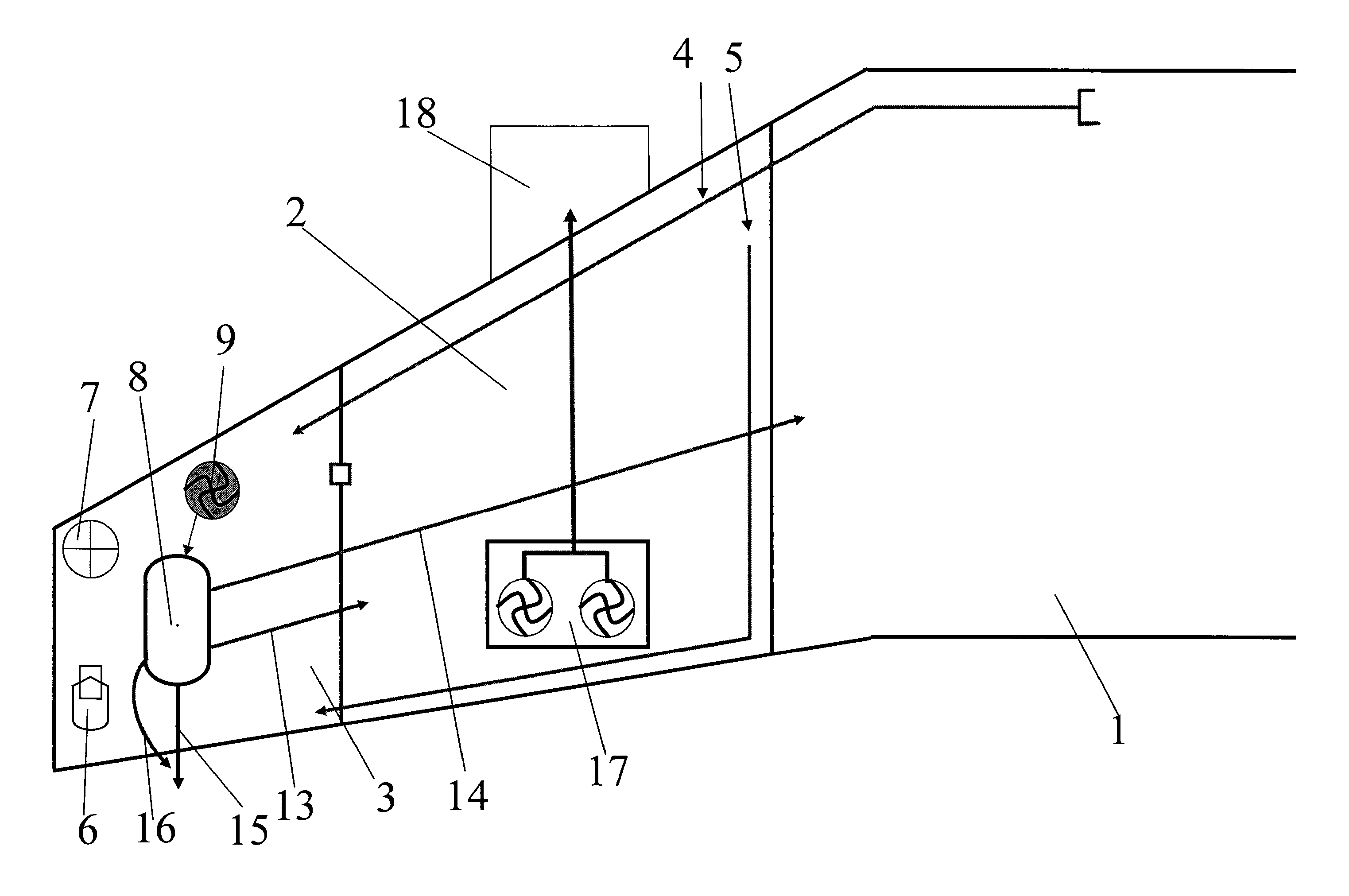
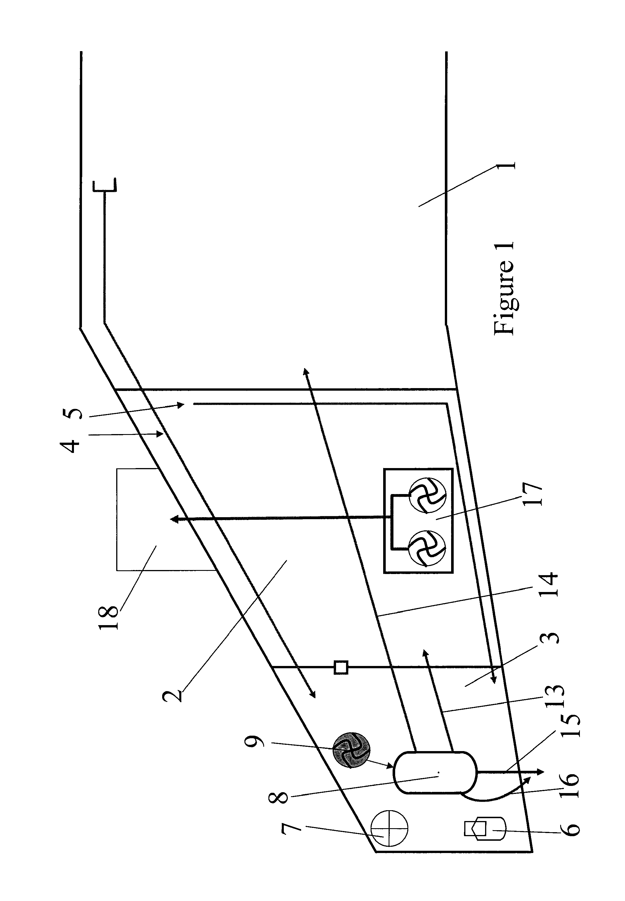
[0031]FIG. 1 illustrates schematically the left hand side of an aircraft fuel system having a three-tank configuration. The fuel system includes a centre tank 1, a left wing tank 2 and a right wing tank (not shown). The fuel system includes a ventilation system including a left vent tank 3 and a right vent tank (not shown). The left vent tank 3 ventilates the ullage of the centre tank 1 and the ullage of the left wing tank 2 by means of first vent lines 4, 5. Similarly, although not shown, the ullage of the right vent tank ventilates the right wing tank by a further first vent line.

[0032]Each vent tank 3 includes a NACA duct assembly 6 including a NACA vent, or NACA scoop, which opens to the ambient atmosphere on the lower aerodynamic surface of the aircraft wing. The vent tanks 3 further include a climb / dive valve 7 which opens to the ambient atmosphere when a pressure differential between the interior of the vent tank and ambient exceeds a predetermined threshold.

[0033]Installed ...


PUM

PropertyMeasurementUnit
pressureaaaaaaaaaa
temperatureaaaaaaaaaa
catalytic temperatureaaaaaaaaaa

Abstract

A fuel system comprising a fuel tank, a vent tank having a duct open to the ambient atmosphere, a first vent line fluidically connecting the fuel tank ullage to the vent tank, a gas drying system including a pump and a dehumidifying device disposed within the vent tank, and a second vent line fluidically connecting a dry gas outlet of the dehumidifying device to the ullage, wherein the pump is operable to maintain a higher pressure within the ullage than in the vent tank so as to drive vapor rich gas from the ullage into the vent tank via the first vent line. Also, a method of operating the fuel system and a method of retro-fitting the gas drying system in an existing fuel system. The gas drying system may optionally be a gas drying / inerting system.

Description

RELATED APPLICATIONS[0001]The present application is a National Phase of PCT / GB2011 / 050535, filed Mar. 17, 2011 and is based on, and claims priority from, Great Britain Application Number 1004837.9, filed Mar. 23, 2010.FIELD OF THE INVENTION[0002]The present invention relates to a fuel system and to a method of operating the fuel system.BACKGROUND OF THE INVENTION[0003]Water is an unavoidable contaminant in fuel. It can affect fuel system component reliability and lead to operational delays and increased maintenance activities. In addition, the propensity for microbiological contamination is directly proportional to the presence of water and the temperature within fuel tanks. Sources of water in fuel tanks is from fuel loaded into the fuel tank during refuel (dissolved water) and from air entering the fuel tank via its ventilation system.[0004]Most existing solutions for water management in fuel tanks involve either scavenging water in the liquid phase within the fuel tank, or proce...

Claims


Application Information

Patent Timeline
Patent Type & Authority Patents(United States)
IPC IPC(8): B64D37/34B01D53/86F26B21/08B01D53/26B64D37/32
CPCB01D2257/104Y02T50/44B64D37/32B01D2259/4575B64D37/34B01D2259/4516B01D53/265B01D53/8671Y02T50/40
Inventor TICHBORNE, FRANKLINLAM, JOSEPH K-WPARMENTER, DAVIDMASTERS, SIMON
Owner AIRBUS OPERATIONS LTD
Why Eureka
Try Eureka