

Inerting method for preventing and/or extinguishing fire as well as inerting system to realize the method
a technology of inerting system and fire, which is applied in the direction of dispersed particle separation, dental surgery, separation processes, etc., can solve the problems of increasing the air factor, affecting the runtime of the compressor, and affecting the efficiency of the compressor
- Summary
- Abstract
- Description
- Claims
- Application Information
AI Technical Summary
Problems solved by technology
Method used
Image

Examples
third embodiment
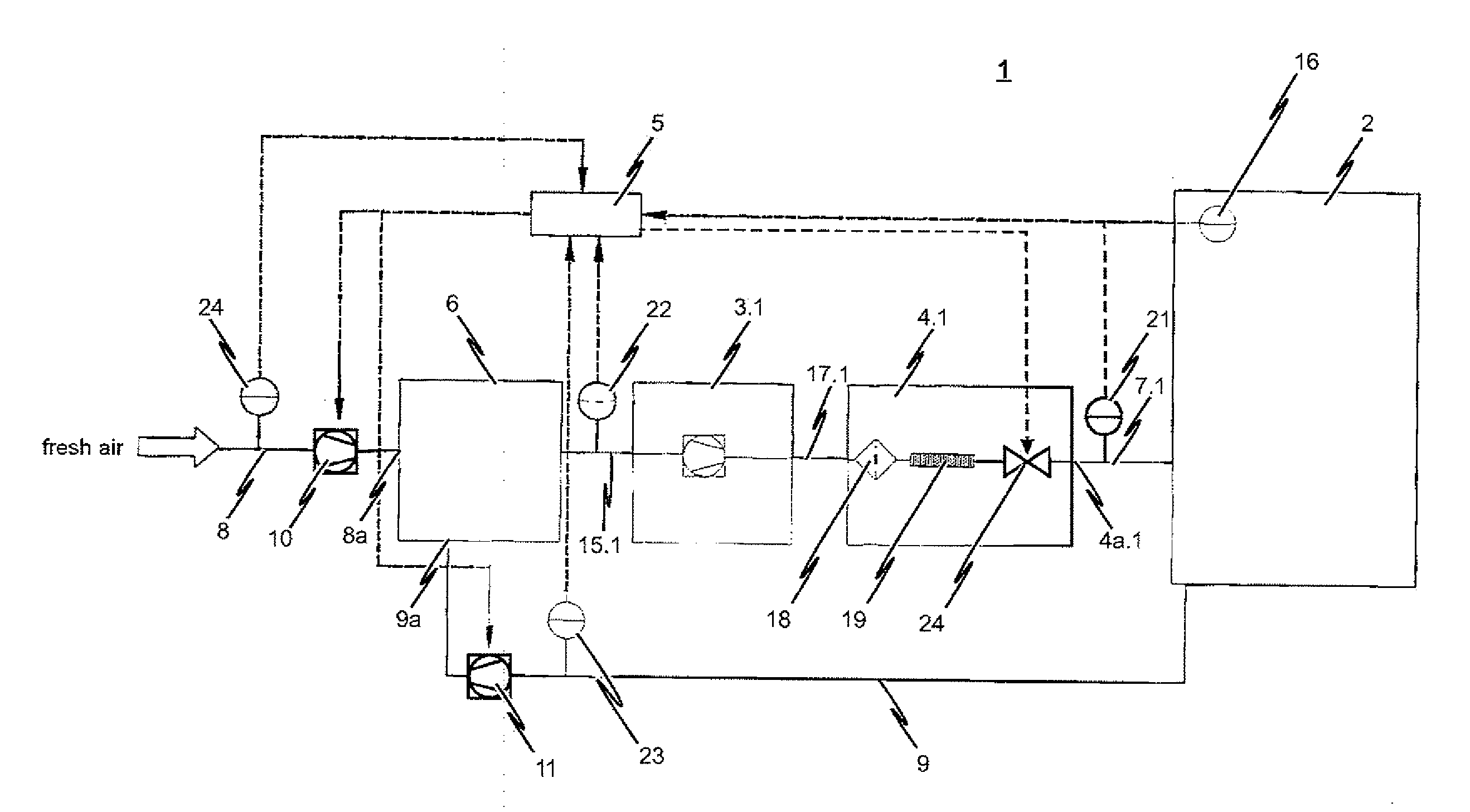
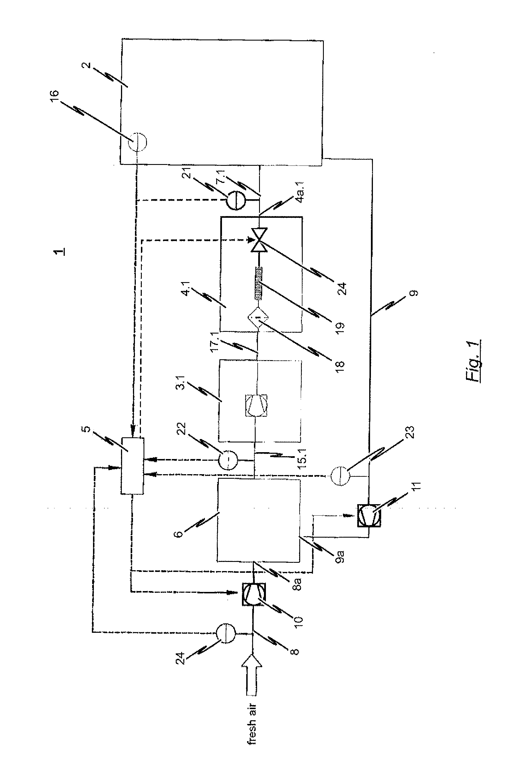
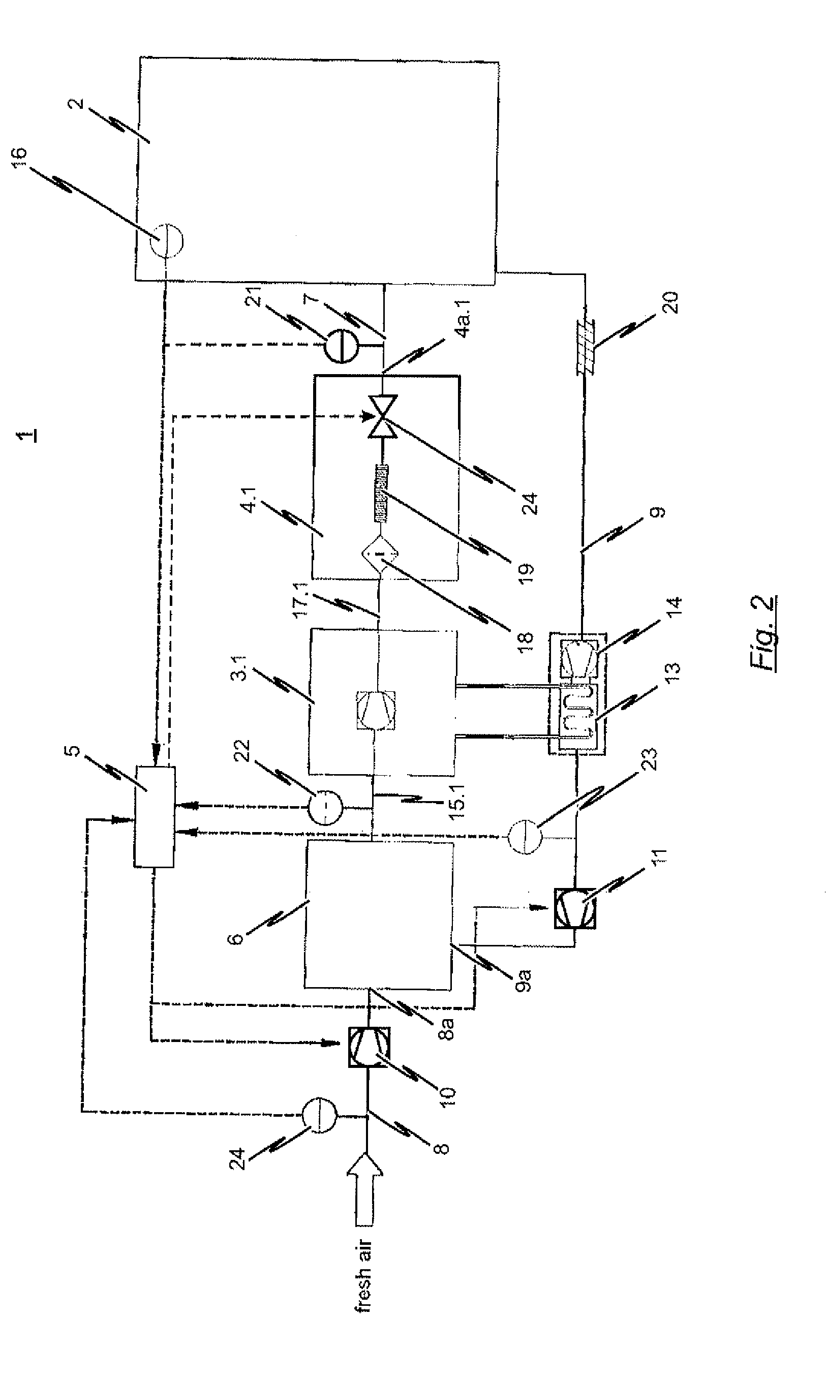
[0086]FIG. 3 shows a schematic view of an inerting system 1 according to the present invention. The design and functioning of the inerting system 1 according to the embodiment depicted in FIG. 3 substantially corresponds to the design and functioning of the inerting system described above with reference to FIG. 1 so that to avoid repetition, the following will only address the differences.
[0087]As FIG. 3 shows, the mixing chamber of the embodiment depicted therein is realized as a filter 6′. The mixing chamber realized as a filter 6′ thus fulfills two functions: on the one hand, it serves to provide the initial gas mixture, and does so by mixing the fresh air supplied by the fresh air supply line system with the ambient air withdrawn from room 2 supplied by the return line system 9. On the other hand, the mixing chamber realized as filter 6′ serves to filter the provided initial gas mixture prior to it being compressed by means of compressor 3.1. This thus dispenses with the need fo...
fourth embodiment
[0089]The design and functioning of the inerting system 1 is essentially identical to the embodiment described above with reference to the FIG. 1 depiction, albeit the embodiment according to FIG. 4 makes use of a plurality of nitrogen generators 4.1, 4.2 and 4.3 connected in parallel. Each nitrogen generator 4.1, 4.2, 4.3 is respectively associated with a compressor 3.1, 3.2, 3.3 which is connected to the mixing chamber 6 by means of a corresponding line system 15.1, 15.2, 15.3 so as to suction off the necessary initial gas mixture from the mixing chamber 6 for the associated nitrogen generator 4.1, 4.2, 4.3 and to compress it to the pressure value required for the optimum operation of the respective nitrogen generator 4.1, 4.2, 4.3. Each nitrogen generator 4.1, 4.2, 4.3 utilized in the inerting system 1 according to the embodiment depicted in FIG. 4 is connected to the enclosed room 2 by means of a corresponding supply line 7.1, 7.2, 7.3. Hence, the gas separation system depicted...
fifth embodiment
[0129]In contrast to this fifth embodiment depicted in FIG. 9, such an additional line 42 between the mixing chamber 6 and a vacuum pressure swing adsorption generator 4.3 through the intermediary connection of a correspondingly controllable intermediate valve 41 can then however also be an advantage in the absence of a great plurality of gas separation systems 3.1, 4.1; 3.2, 4.2; 3.3, 4.3 or when nitrogen generators 4.1, 4.2, 4.3 utilizing different gas separation techniques are not employed. Even just providing one vacuum pressure swing adsorption generator 4.3 yields the advantage that, given the appropriate dimensioning of the mixing chamber 6, the passive pressure equalization can be regulated by the intermediate valve 41 prior to the end of the desorption phase of the vacuum pressure swing adsorption generator 4.3 allows the associated compressor 3.3 to be operated for a shorter amount of time in total, thereby providing an energy-saving effect.
[0130]A sixth exemplary embodime...
PUM
| Property | Measurement | Unit |
|---|---|---|
| Pressure | aaaaa | aaaaa |
| Pressure | aaaaa | aaaaa |
| Pressure | aaaaa | aaaaa |
Abstract
Description
Claims
Application Information