Spring rockflex bearing arm

a bearing arm and spring technology, applied in the direction of harrows, ploughs, drags, etc., can solve the problems of disc breakage, disc breakage, and different types of damage to the implemen

Inactive Publication Date: 2002-09-12
SALFORD FARM MACHINERY
View PDF0 Cites 10 Cited by
  • Summary
  • Abstract
  • Description
  • Claims
  • Application Information

AI Technical Summary

Problems solved by technology

Impact of the discs with a sub-terranean obstacle, such as a rock, causes the entire implement to be lifted out of the soil in order to pass over the obstacle and can cause damage to the implement.
Types of damage include broken or bent discs, bent or broken gang shafts and bearing failures due to twisting or asymmetric loading of the gang shaft.
Since the mount must be sufficiently stiff to resist deflection of the gang during normal operation, the C-shaped mount is quite stiff and does not easily deflect.
Due to its stiffness, the C-shaped mount is prone to breakage when a particularly large obstacle is encountered.
Also, the amount of force required to cause deflection is not readily adjustable and the mount provides very little range of vertical motion for the disc gang.
Accordingly, the C-shaped mount has proven relatively ineffective at preventing damage to the implement.
Since the bearing is fixed with respect to the second structural support member and pivots in the same vertical plane, the angled orientation of the shaft places an asymmetric load on the bearing, leading to premature bearing wear and excessive bearing maintenance.

Method used


Image

  • Spring rockflex bearing arm
  • Spring rockflex bearing arm
  • Spring rockflex bearing arm

Examples


Embodiment Construction

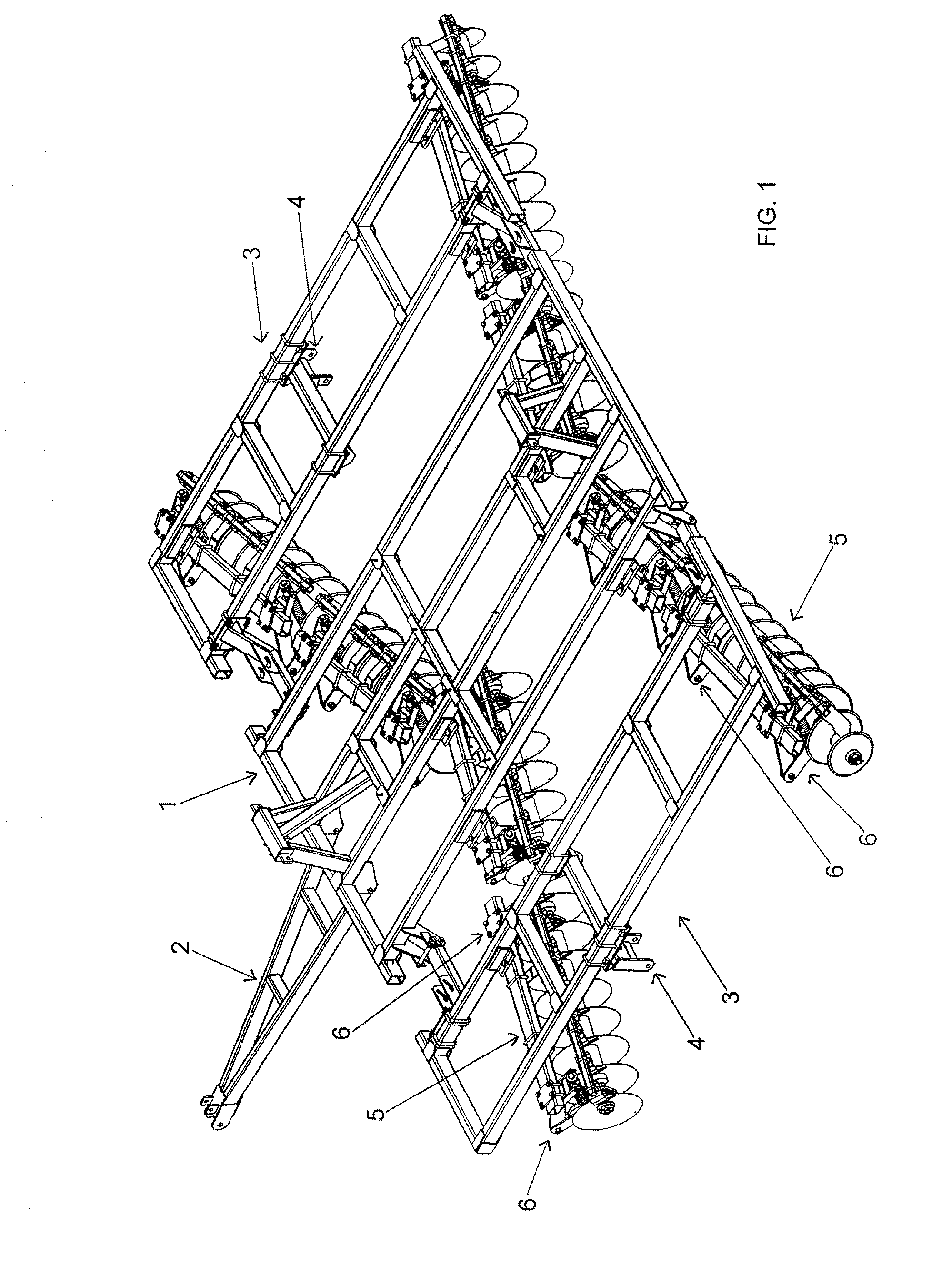
[0020] With reference to FIG. 1, a disc harrow is shown having a frame 1 and a tongue 2, adapted for conventional attachment to the drawbar of a tractor using a draw pin. The frame has folding wings 3 to permit the overall width of the implement to be decreased for road travel. The frame is provided with mounts 4 for wheels (not shown) that permit the disc harrow to be transported when the wheels are in the lowered position with reference to the frame 1. A plurality of disc gangs 5 is shown, each attached to the underside of the frame at an angle to the forward direction of travel by a plurality of coil spring mounts 6 as will hereinafter be more thoroughly described.

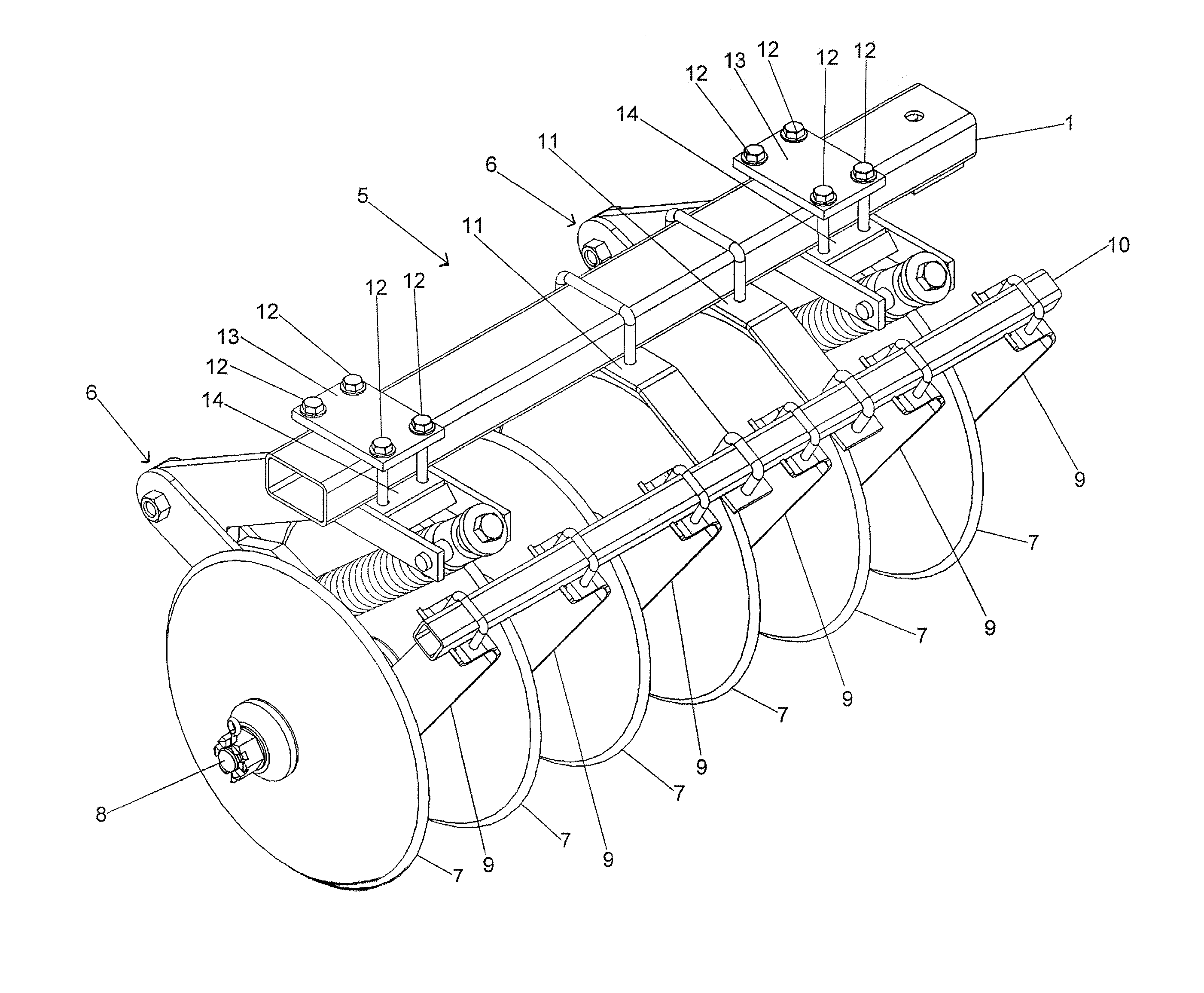
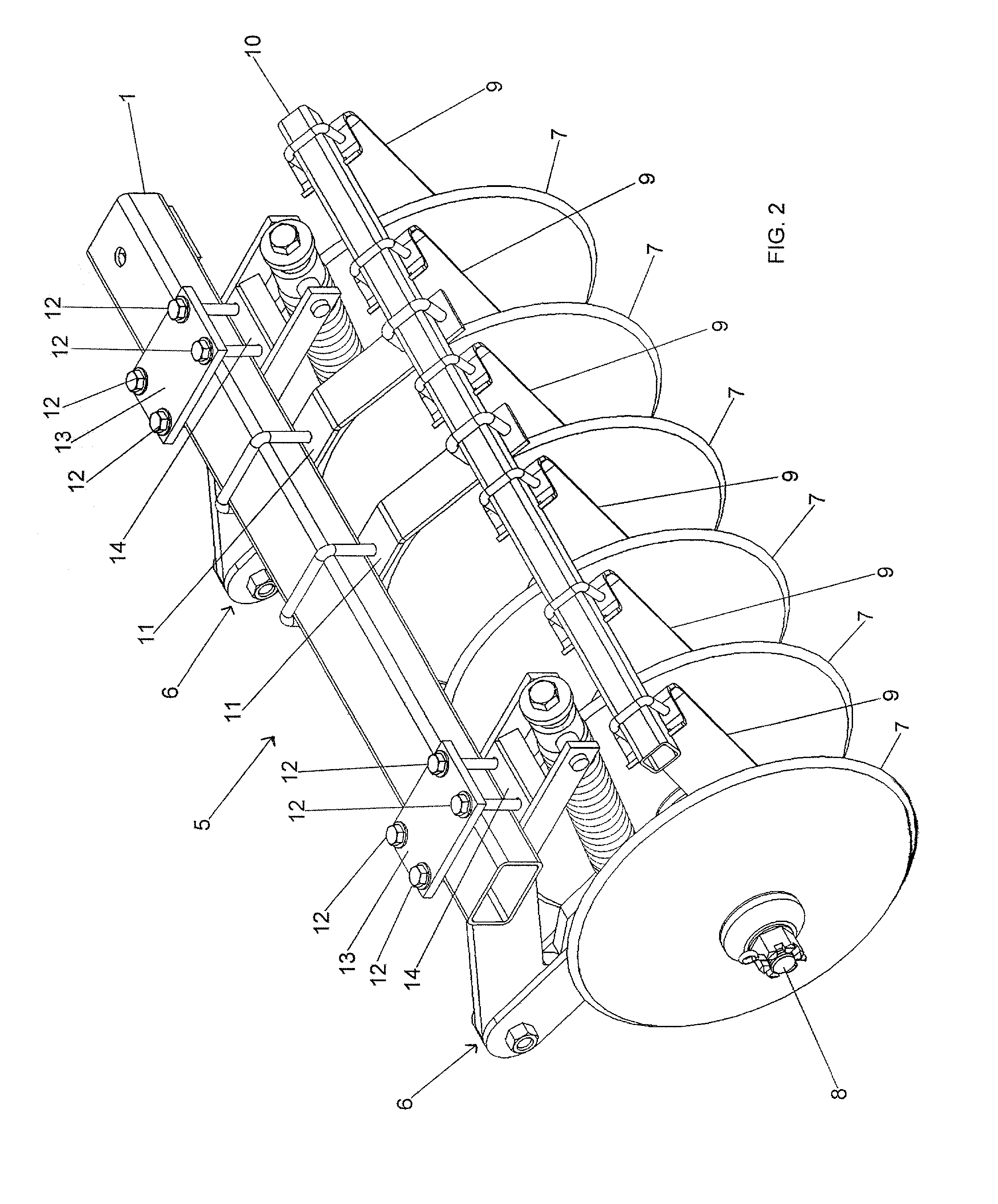
[0021] With reference to FIGS. 2 and 3, the disc gang 5 is comprised of a plurality of concavely shaped earth working discs 7, each having an aperture at its center for passage of a gang shaft 8 therethrough. The discs 7 are oriented substantially parallel to each other and spaced apart at uniform intervals along the le...


PUM


Abstract

A disc harrow has a frame and a plurality of earth working discs. Each disc has a central aperture for attachment to a gang shaft. A mount attaches the gang shaft to the underside of the frame and has bearings to permit rotation of the shaft in response to forward movement of the disc harrow. The mount includes a first structural member, a second structural member and a resilient spring connected between the two members. In operation, upon striking of an obstacle by the discs, the gang shaft is permitted to upwardly deflect by the mount to prevent damage to the disc harrow. The second structural member has first and second portions with aligned longitudinal axes. The first and second portions are rotationally connected to permit rotation of the second portion in response to an angular moment applied to the second portion by deflection of the gang shaft. The rotational connection permits the bearing to automatically maintain a preferred alignment with the gang shaft during deflection, thereby preventing damage to the bearing.

Description

[0001] This patent application claims priority from U.S. Provisional Patent Application No. 60 / 273,351 filed on Mar. 6, 2001.[0002] 1. Field of the Invention[0003] The invention relates to a disc harrow farm implement. The disc harrow has a frame with an attached disc gang comprising a plurality of ground engaging discs attached to a gang shaft. In particular, the present invention relates to a novel linkage arrangement for attaching the disc gang to the frame.[0004] 2. Description of the Prior Art[0005] The disc harrow is a farm implement that is used to turn and mix soil. The disc harrow includes a frame that is towed behind a tractor with a plurality of earth working disc shaped blades, or discs that engage the ground. Each disc is normally concave and the center of each disc has an aperture for mounting the disc on a gang shaft. A plurality of substantially parallel discs mounted to the shaft at uniformly spaced apart intervals along its length is referred to as a disc gang. Eac...

Claims


Application Information

Patent Timeline
Patent Type & Authority Applications(United States)
IPC IPC(8): A01B21/08A01B23/04A01B61/04
CPCA01B21/08A01B61/046
Inventor ROZENDAAL, JACOBUS A.
Owner SALFORD FARM MACHINERY
Why Eureka
Try Eureka