High-frequency amplifier circuit having a directly-connected bias circuit
a bias circuit and amplifier circuit technology, applied in the field of transistor amplifier circuits, can solve the problems of increasing power loss in the circuit, loss that is quite significant, and mismatch between the transistor pair, so as to minimize mismatch and minimize power loss
- Summary
- Abstract
- Description
- Claims
- Application Information
AI Technical Summary
Benefits of technology
Problems solved by technology
Method used
Image
Examples
Embodiment Construction
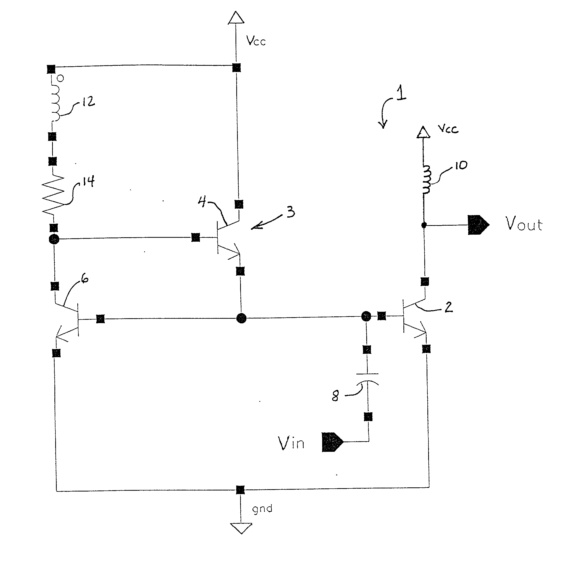
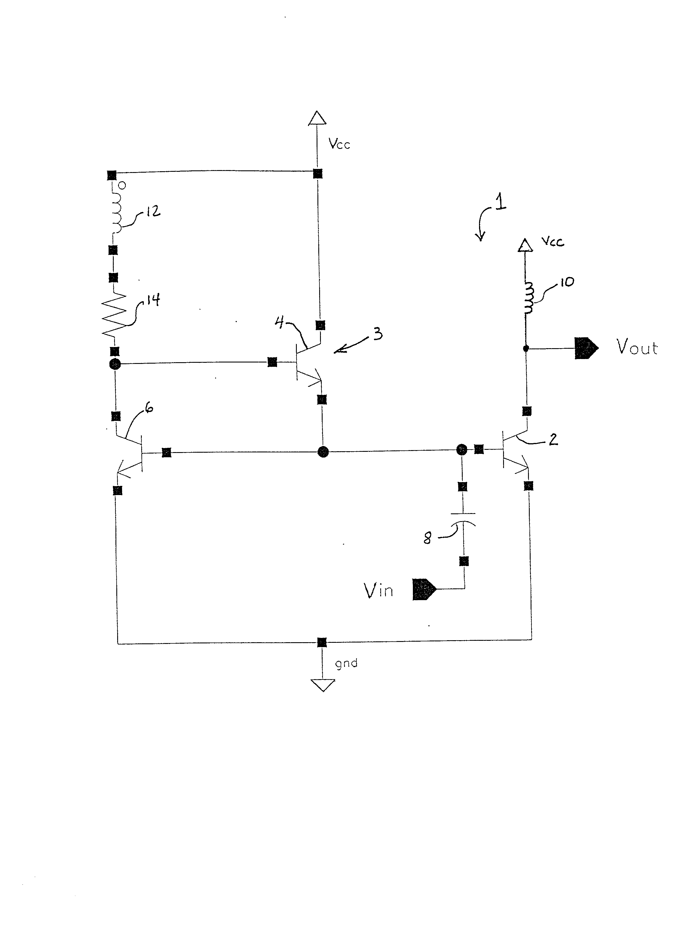
[0013] A simplified schematic diagram of a high-frequency amplifier circuit 1 is shown in the single FIGURE of the drawing. The amplifier circuit 1 includes an amplifying transistor 2 and a bias circuit 3 having a bias transistor 4 which has its emitter directly connected to the base of the amplifying transistor 2. The bias circuit 3 also includes an additional transistor 6 having its collector connected to the base of transistor 4 and its base connected to the emitter of transistor 4. In the illustrative embodiment shown, transistor 6 is configured in a common-emitter mode and transistor 4 is configured in an emitter-follower mode of operation.
[0014] An RF signal to be amplified is provided at terminal Vin through a coupling capacitor 8 to the base of transistor 2, and an amplified output signal is taken from the collector of transistor 2 at terminal Vout, which is also coupled to a power supply terminal Vcc through an inductor 10. The bias circuit 3 and amplifying transistor 2 are...
PUM
 Abstract
Description
Claims
Application Information
 - R&D
- Intellectual Property
- Life Sciences
- Materials
- Tech Scout
- Unparalleled Data Quality
- Higher Quality Content
- 60% Fewer Hallucinations
Browse by: Latest US Patents, China's latest patents, Technical Efficacy Thesaurus, Application Domain, Technology Topic, Popular Technical Reports.
© 2025 PatSnap. All rights reserved.Legal|Privacy policy|Modern Slavery Act Transparency Statement|Sitemap|About US| Contact US: help@patsnap.com


