Optical transmission apparatus with an optimal routing and data transmitting capability and a method of determining an optimal route on optical transmission

Active Publication Date: 2002-09-12
OKI ELECTRIC IND CO LTD
View PDF3 Cites 47 Cited by
  • Summary
  • Abstract
  • Description
  • Claims
  • Application Information

AI Technical Summary

Benefits of technology

0009] It is an object of the present invention to provide an optical transmission apparatus capable of selecting a r

Problems solved by technology

When such route conditions other than the number of hops are taken into account, a transmis

Method used


Image

  • Optical transmission apparatus with an optimal routing and data transmitting capability and a method of determining an optimal route on optical transmission
  • Optical transmission apparatus with an optimal routing and data transmitting capability and a method of determining an optimal route on optical transmission
  • Optical transmission apparatus with an optimal routing and data transmitting capability and a method of determining an optimal route on optical transmission

Examples


Embodiment Construction

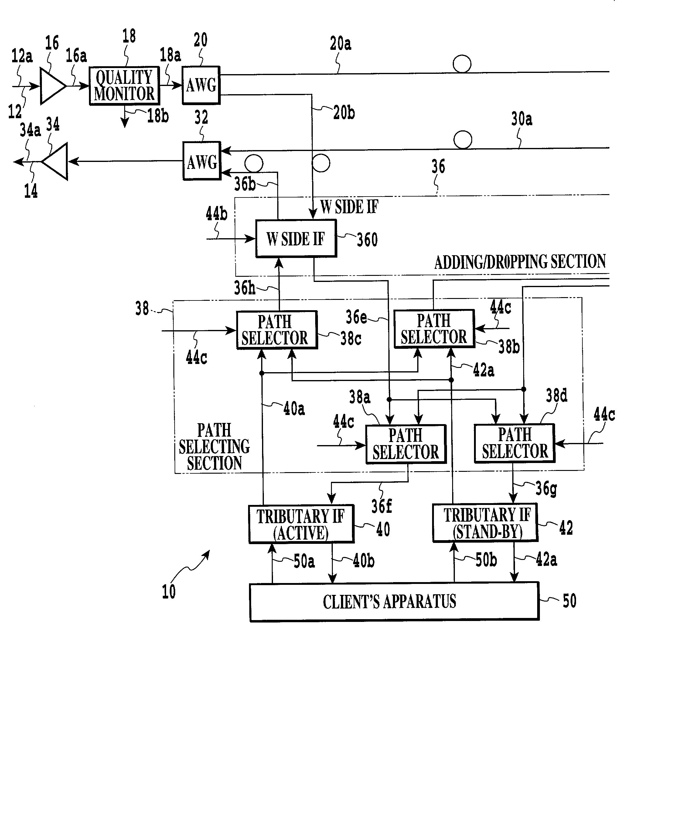
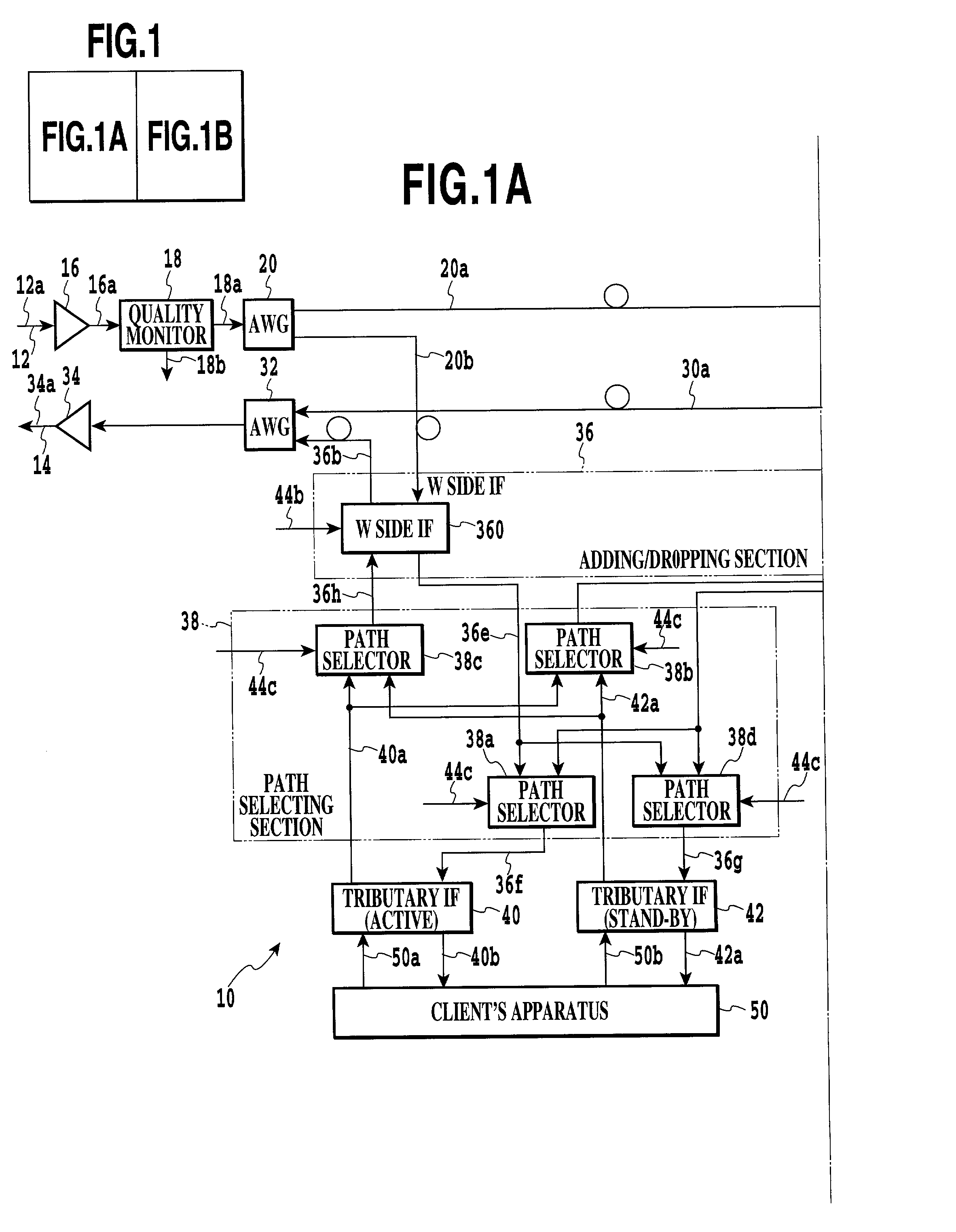
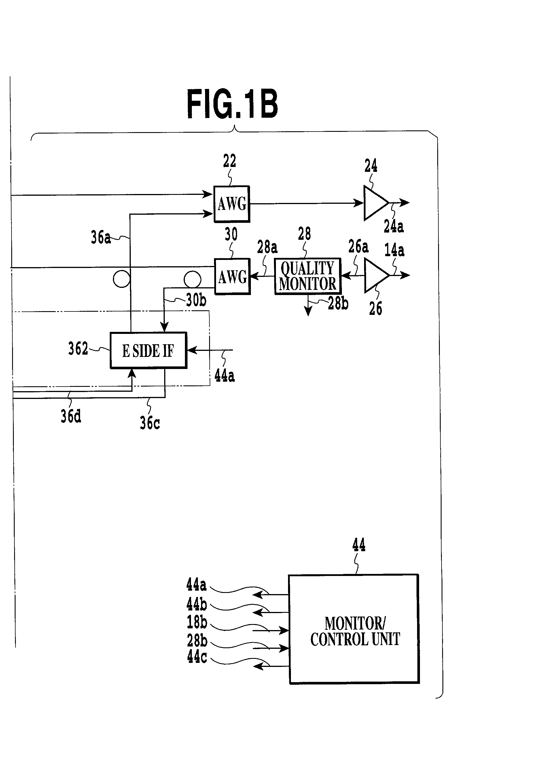
[0021] Referring to FIGS. 1A and 1B, an optical transmission apparatus embodying the present invention is shown and implemented as an OADM by way of example. In FIGS. 1A and 1B, part of the OADM not relevant to the understanding of the illustrative embodiment is not shown. Signals are designated by reference numerals attached to connect lines on which they appear.

[0022] As shown in FIGS. 1A and 1B, the OADM, generally 10, is connected to ring type, bidirectional communication paths. In the illustrative embodiment, the communication paths are implemented by an inner ring 12 and an outer ring 14 constituted by respective optical fiber cables. FIGS. 1A and 1B show part of such a ring type network.

[0023] The OADM 10 includes an optical input amplifier 16, a quality monitor 18, AWGs (Arrayed Waveguide Gratings) 20 and 22, and an optical output amplifier 24 that are allocated to the inner ring 12. An optical input amplifier 26, a quality monitor 28, AWGs 30 and 32 and an optical output am...


PUM


Abstract

An optical transmission apparatus implemented as an OADM (Optical Add/Drop Multiplexer) includes quality monitors each for monitoring the quality of a signal arriving on a particular optical transmission path. A monitor/control unit converts quality signals output from the quality monitors to path-by-path bit error rates, or estimation values, and compares them to select a route. The monitor/control unit then generates a metric value "1" for the route selected and adds it to one of identical metric values, which are assigned to routes to the same destination, that corresponds to the route selected. The monitor/control unit can therefore select a route closer to actual transmission path conditions. A method of determining an optimal route for optical transfer is also disclosed.

Description

BACKGROUND OF THE INVENTION[0001] 1. Field of the Invention[0002] The present invention relates to an optical transmission apparatus and a method of determining an optimal optical transmission route advantageously applicable to the routing system of, among various communication apparatuses, an optical transmission apparatus.[0003] 2. Description of the Background Art[0004] Networks in general include a ladder type network and a ring type network. A ring type network includes ADMs (Add / Drop Multiplexers) for multiplexing optical signals to be output to ring transmission paths and demultiplexing optical signals input from the transmission paths. ADMs using optical fiber cables as the ring transmission paths are referred to as OADMs (Optical ADMs). An OADM differs from an ADM in that it has a bridging or through function between two transmission paths in addition to a multiplexing and demultiplexing function. Further, an OADM has a function of selecting a route along which a signal sho...

Claims


Application Information

Patent Timeline
IPC IPC(8): H04B10/03H04B10/032H04B10/07H04B10/077H04B10/275H04B10/291H04J14/02H04L12/437H04L12/701H04L29/02
CPCH04J14/0201H04J14/0206H04J14/0212H04J14/0213H04J14/0221H04J14/0227H04J14/0283H04J14/0241
Inventor UEMATSU, KIYOSHIWAKABAYASHI, MANABU
Owner OKI ELECTRIC IND CO LTD
Why Eureka
Try Eureka